2. 中国石油大庆油田分公司 井下作业分公司,黑龙江 大庆 163311
2. Downhole Service Company, PetroChina Daqing Oilfield Company, Daqing 163311, Heilongjiang, China
化学驱已成为国内外大多油田提高采收率的主要方法,其中聚合物驱技术是应用最广泛的方法[1],以大庆油田为例,已有50余个区块成功开展了工业化规模的聚合物驱油。相较于水驱,聚合物驱采收率平均提高了约13%,正在实施的二类油层聚合物驱提效项目,也有望在水驱基础上提高原油采收率10%以上[2-5]。注聚过程中为了提高井注入能力,往往会提高其注入压力,当注入压力高于地层破裂压力时,将在近井地带形成诱导裂缝[6],给油藏进一步挖潜带来困难。因此,明确诱导裂缝特征及参数成为国内外学者研究的热点。
关于诱导裂缝对压力动态的影响研究人员已做过很多研究。Hagoort[7]首先给出注水诱导裂缝的概念,并提出可采用与井筒储集效应相似的变流量方法求解关井压力测试时裂缝闭合导致的流量变化;Koning[8]在Hagoort的基础上利用拉氏变换等方法求解出二维瞬态椭圆方程的解析解,给出了在裂缝存在条件下水驱的压力动态;Hoek等[9-10]研究了水驱在考虑动态裂缝闭合不同边界条件下的井底压力解,在处理裂缝闭合时,将裂缝储集系数分为常数及随压力变化2种情况,并给出无限导流裂缝闭合的解析解及半解析解。国内学者对诱导裂缝成因机理及其延伸规律以及注水诱导裂缝关井闭合的压力动态曲线也进行了相关研究[11-13]。
在实际水驱开发后的注聚阶段,由于聚合物具有剪切变稀、浓度扩散、渗透率下降等特征[14],考虑诱导裂缝闭合条件下的数学模型的数值求解就显得尤为方便,PEBI变尺度混合网格及其符合物理渗流的网格划分在数值计算中凸显优势[15-16]。为此,本文采用数值试井方法,基于PEBI网格剖分,综合考虑聚合物溶液黏浓关系、剪切效应、渗透率下降以及吸附机理,建立考虑诱导裂缝的聚合物驱垂直裂缝井数学模型,并对注聚井压力动态曲线特征及影响因素进行分析,形成考虑诱导裂缝闭合的注聚井压力降落动态研究方法。该研究结果可进一步拓展注聚井压力动态分析方法,以期为准确认识诱导裂缝规模及参数提供重要的理论支持。
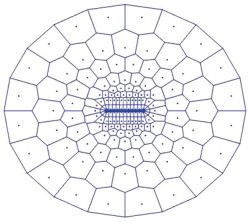
1 物理模型的建立 1.1 混合PEBI网格剖分方法网格剖分是油藏空间离散的基础,在渗流过程中PEBI网格剖分可分为圆模块、圆角矩形模块、平面模块几种形式[15]。PEBI网格的优势在于可利用变尺度缩小网格节点数目,减少计算量,且网格剖分更符合物理渗流过程,描述流动更准确。
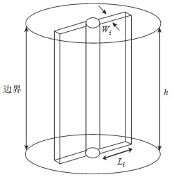
1.2 物理模型假设无限大地层中有一口注聚井,一条与井筒共面的垂直诱导裂缝,且在垂直方向上贯穿整个油层,以定流量Q注入,建立考虑诱导裂缝的均质油藏聚合物驱垂直裂缝井物理模型(图 1)。对含垂直裂缝井的无限大地层进行空间离散,在裂缝周围采用复合线性流动的圆角矩形模块进行网格剖分;在远井地带,采用复合椭圆及径向流特征的变尺度网格剖分(图 2)。
|
下载原图 图 1 垂直裂缝井物理模型 h为地层厚度,m;Wf为裂缝宽度,m;Lf为裂缝半长,m Fig. 1 Physical model of vertically fractured well |
|
下载原图 图 2 垂直裂缝井数值试井网格剖分示意图 Fig. 2 Schematic diagram of grid generation in vertically fractured well |
假设条件:外边界无限大,地层上下为不渗透边界,诱导裂缝关于井筒对称,裂缝末端封闭;诱导裂缝内压力相同;单相微可压缩流体流动;考虑井筒储存和表皮效应。
2 聚合物渗流特征数学模型 2.1 浓度分布模型聚合物溶液在多孔介质内流动,会发生浓度扩散与对流作用,综合Fick定律、对流通量变化及物质守恒原理,得到聚合物溶液在地层中浓度扩散方程的散度形式为
| $ \operatorname{div}\left(D \cdot \nabla C_{\mathrm{p}}\right)-\frac{Q}{2 {\rm{ \mathsf{ π} }} r h \varphi} \cdot \operatorname{div}\left(C_{\mathrm{p}}\right)=\frac{\partial C_{\mathrm{p}}}{\partial t} $ | (1) |
式中:Q为流量,m3/s;r为网格到井中心的径向距离,m;h为地层厚度,m;φ为孔隙度,%;D为扩散系数,m2/s;t为时间,s;Cp为聚合物质量浓度,kg/m3。
2.2 黏度模型
聚合物溶液的黏度与其在多孔介质内的浓度及剪切速率有关。聚合物溶液黏度μp、剪切速率
| $ \mu_{p}=\mu_{\infty}+\frac{\mu_{0}-\mu_{\infty}}{1+\left(\frac{\dot{\gamma}}{\dot{\gamma}_{1 / 2}}\right)^{P_{\alpha}-1}} $ | (2) |
式中:μp为聚合物流动时的有效黏度,Pa·s;μ∞为剪切率趋于无穷大时聚合物溶液黏度,近似等于水的黏度,Pa·s;μ0为聚合物零剪切黏度,Pa·s;
零剪切黏度与浓度的关系可表示为
| $ \mu_{0}=\mu_{\mathrm{w}}\left[1+\left(A_{1} C_{\mathrm{p}}+A_{2} C_{\mathrm{p}}^{2}+A_{3} C_{\mathrm{p}}^{3}\right)\right] $ | (3) |
式中:A1,A2,A3为与聚合物溶液有关的常数,其单位分别为(kg/m3)-1,(kg/m3)-2和(kg/m3)-3;μw为水的黏度,Pa·s。
2.3 渗透率模型聚合物溶液在多孔介质流动过程中,往往伴随着吸附滞留现象,增大附加阻力从而导致地层渗透率下降,通过引入渗透率下降系数Rk来修正渗透率模型,建立聚合物溶液修正渗透率模型[18]。
| $ R_{\mathrm{k}}=1+\frac{\left(R_{\mathrm{k} \max }-1\right) b_{\mathrm{p}} C_{\mathrm{p}}}{\left(1+b_{\mathrm{p}} C_{\mathrm{p}}\right)} $ | (4) |
式中:bp为实验确定常数,10-4;Rk max[19]为最大渗透率下降系数,1.621。
渗透率模型为
| $ K_{\mathrm{p}}=\frac{K}{R_{\mathrm{k}}} $ | (5) |
式中:K为地层渗透率,mD;Kp考虑聚合物吸附作用后的渗透率,mD。
3 考虑诱导裂缝聚合物驱垂直裂缝井数学模型 3.1 模型的建立考虑诱导裂缝的均质油藏聚合物驱垂直裂缝井数值试井模型主要包括基本渗流微分方程,井以定产量生产、外边界无限大的边界条件以及初始条件3个部分,由此建立考虑诱导裂缝的聚合物驱垂直井数值试井数学模型。
运动方程为
| $ v=-\frac{1 \times 10^{-15} K_{\mathrm{p}}}{\mu_{\mathrm{p}}} \nabla P $ | (6) |
式中:v为渗流速度,m/s;
液体状态方程为
| $ B=\frac{B_{0}}{1+C_{\mathrm{L}}\left(P-P_{a}\right)} $ | (7) |
式中:B为体积系数;B0为原始体积系数;CL为液体压缩系数,Pa-1;P为网格压力,Pa;Pa为原始大气压,Pa。
岩石状态方程为
| $ \varphi=\varphi_{0}\left[1+C_{\mathrm{f}}\left(P-P_{\mathrm{a}}\right)\right] $ | (8) |
式中:φ0为原始孔隙度,%;Cf为岩石压缩系数,Pa-1。
连续性方程为
| $ \operatorname{div}(\rho v)+\frac{\partial(\rho \varphi)}{\partial t}=0 $ | (9) |
式中:ρ为流体密度,kg/m3。
将式(6)、式(7)、式(8)同时代入式(9)中,得到考虑诱导裂缝的均质油藏单相流数值试井模型微分方程
| $ \operatorname{div}\left(\frac{1 \times 10^{-15} K_{\mathrm{p}}}{\mu_{\mathrm{p}} B} \nabla P\right)=\frac{\partial}{\partial t}\left(\frac{\varphi}{B}\right) $ | (10) |
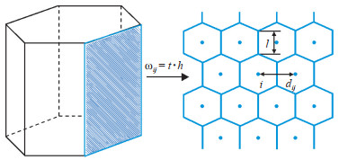
有限体积法具有处理复杂边界渗流问题的优越性,本文采用有限体积法进行离散求解。PEBI网格单元与其邻接网格关系如图 3所示。
|
下载原图 图 3 PEBI网格单元示意图 Fig. 3 Schematic diagram of PEBI grid cell |
首先对浓度方程在控制体内进行积分
| $ \left.\int\limits_{t_{n}}^{t_{n}+1} \int\limits_{V} \operatorname{div}\left(D \cdot \nabla C_{\mathrm{p}}\right)-\frac{Q}{2 {\rm{ \mathsf{ π} }} r h \varphi} \cdot \operatorname{div}\left(C_{\mathrm{p}}\right)\right] \mathrm{d} V \mathrm{d} t=\int\limits_{t_{n}}^{t_{n}+1} \int\limits_{V} \frac{\partial C_{\mathrm{p}}}{\partial t} \mathrm{d} V \mathrm{d} t $ | (11) |
根据高斯定理,将体积积分[式(11)]转化为面积积分,再根据PEBI网格特点,得到质量浓度方程离散形式为
| $ \begin{aligned} \sum\limits_{j} D \cdot &G_{i j}\left[\left(C_{\mathrm{p}}\right)_{j}-\left(C_{\mathrm{p}}\right)_{i}\right]^{n+1}-\frac{Q}{2 {\rm{ \mathsf{ π} }} r h \varphi}\left(C_{\mathrm{p}}\right)_{j}^{n} V_{j}= \\ &\frac{V_{i}}{\Delta t}\left[\left(C_{\mathrm{p}}\right)_{i}^{n+1}-\left(C_{\mathrm{p}}\right)_{i}^{n}\right] \end{aligned} $ | (12) |
对式(10)在控制体积和时间段上积分,得到
| $ \int\limits_{t_{n}}^{t_{n+1}} \int\limits_{V} \operatorname{div}\left(\frac{1 \times 10^{-15} K_{\mathrm{p}}}{\mu_{\mathrm{p}} B} \nabla P\right) \mathrm{d} V \mathrm{d} t \int\limits_{t_{n}}^{t_{n+1}} \int\limits_{V} \frac{\partial}{\partial t}\left(\frac{\varphi}{B}\right) \mathrm{d} V \mathrm{d} t $ | (13) |
根据高斯定理,将式(13)左边的体积分简化为网格单元界面周围的面积分
| $ \int\limits_{t_{n}}^{t_{n+1}} \int\limits_{V} \operatorname{div}\left(\frac{1 \times 10^{-15} K_{\mathrm{p}}}{\mu_{\mathrm{p}} B} \nabla P\right) \mathrm{d} V \mathrm{d} t=\int\limits_{t_{n}}^{t_{n}+1} \int\limits_{V} \operatorname{div}\left(\frac{1 \times 10^{-15} K_{\mathrm{p}}}{\mu_{\mathrm{p}} B} \nabla P\right) \mathrm{d} S \mathrm{d} t=\int\limits_{t_{n}}^{t_{n+1}} \sum\limits_{j} \frac{1 \times 10^{-15} K_{\mathrm{p}}}{\mu_{\mathrm{p}} B} \frac{\left(P_{j}-P_{i}\right)^{n}}{d_{i j}} \omega_{i j} \mathrm{d} t $ | (14) |
由于PEBI网格局部正交特性,最终离散得到
| $ \sum\limits_{j} T_{i j}\left(P_{j}-P_{i}\right)^{n+1}=\frac{V_{i}}{\Delta t}\left(P_{i}^{n+1}-P_{i}^{n}\right)\left[\frac{\varphi_{0} C_{\mathrm{f}}+\varphi_{0} C_{\mathrm{L}}}{B_{0}}\right] $ | (15) |
式中:Pi为网格i的压力,Pa;Pj为与网格i邻接的网格j的压力,Pa;Tij为传导系数,为PEBI网格任意2个相邻网格中心点之间的流动系数λij与其几何因子Gij的乘积,m3/(Pa·s);λij为任意2个相邻网格中心点之间的流动系数,m3/(Pa·s);Gij为网格i和j之间的几何因子,m;ωij为相邻网格i,j之间流体流动的截面面积,m2;
对考虑诱导裂缝的聚合物驱垂直裂缝井物理模型进行简化,通过计算得到地层总流量为
| $ \begin{aligned} Q=&Q_{i}^{n+1}+Q_{\mathrm{c}}^{n+1}=\sum\limits_{i}\left[W I_{i} \cdot \lambda\left(P_{\mathrm{wf}}^{n+1}-P_{i}^{n+1}\right)\right]+\\ & \frac{C}{\Delta t}\left(P_{\mathrm{wf}}^{n+1}-P_{\mathrm{wf}}^{n}\right) \end{aligned} $ | (16) |
式中:Qi井筒与相邻网格i间的流量,m3/s;Qc为井筒储集效应的流量,m3/s;Pwf为井底压力,Pa;C为井筒储集系数,m3/Pa;λ为网格i与井筒间的传导率,m2/(Pa·s);WIi为生产指数,m,WIi = θh/[ln(ri/rw)+ S],其中θ为网格i相对井的张开弧度,rad;ri为网格i的径向距离,m;rw为井筒半径,m;S为表皮系数。
结合式(12)、式(15)、式(16)及边界条件得到考虑诱导裂缝的聚合物驱垂直裂缝井数值离散方程,求解得到井底压力动态变化,并对计算结果进行无量纲化,无量纲化的计算公式为
| $ P_{\mathrm{wD}}=\frac{2 \times 10^{-15} {\rm{ \mathsf{ π} }} K h}{Q \mu_{\mathrm{p}} B_{0}}\left(P_{\mathrm{wf}}-p_{i}\right) $ | (17) |
| $ t_{\mathrm{D}}=\frac{1 \times 10^{-15} K}{\varphi_{\mathrm{p}} \mu_{\mathrm{p}} C_{\mathrm{t}} r_{\mathrm{w}}^{2}} t $ | (18) |
| $ C_{\mathrm{D}}=\frac{C}{2 \pi h \varphi_{\mathrm{p}} C_{\mathrm{t}} r_{\mathrm{w}}^{2}} $ | (19) |
| $ F_{\mathrm{CD}}=\frac{K_{\mathrm{f}} w_{\mathrm{f}}}{K L_{\mathrm{f}}} $ | (20) |
式中:PwD为无量纲井底压力;tD为无量纲时间;CD为无量纲井筒储集系数;FCD为无量纲导流系数;Ct为流体和裂缝的总压缩系数,Pa-1;pi为原始地层压力,Pa;rw为井筒半径,m;φp为考虑聚合物吸附作用后的孔隙度,%;Kf为裂缝渗透率,mD。
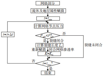
3.3 诱导裂缝闭合模型注聚井关井测压,井底流压PwD逐渐降低,当其降低至低于裂缝开始时的闭合压力PwD0时,诱导裂缝开始闭合。Dam等[20]的实验结果表明,关井测压时诱导裂缝首先从尖端开始闭合,之后逐渐向井筒靠拢。为此本文考虑裂缝横向闭合(图 4),裂缝半长变化满足式(21)[21]。

|
下载原图 图 4 诱导裂缝闭合示意图 0:诱导裂缝未闭合;1:诱导裂缝闭合 Fig. 4 Shematic diagram of induced fracture closure |
| $ \begin{array}{ll} L_{\mathrm{f}}\left(P_{\mathrm{wD}}\right)=L_{\mathrm{f} 0} & P_{\mathrm{wD}}>P_{\mathrm{wD}}^{0} \\ L_{\mathrm{f}}\left(P_{\mathrm{wD}}\right)=L_{\mathrm{f} 0} \times\left(1-\frac{P_{\mathrm{wD}}^{0}-P_{\mathrm{wD}}}{ { delpat }}\right) & P_{\mathrm{wD}} \leqslant P_{\mathrm{wD}}^{0} \end{array} $ | (21) |
式中:Lf为裂缝半长,m;Lf0为初始裂缝半长,m;PwD为井底压力;PwD0为关井后裂缝开始闭合时的压力;delpat为裂缝闭合速度因子。
诱导裂缝闭合会导致其渗透率发生变化,张阳等[22]的研究发现,即使裂缝完全闭合,其渗透率仍比地层渗透率高950.4倍左右。说明即使压裂过程中没有支撑剂,裂缝的存在也可显著提高地层渗流条件。
由此建立动态渗透率模型
| $ \begin{aligned} &K_{\mathrm{f}}(i=0)=K_{\mathrm{f} 0} \\ &K_{\mathrm{f}}(i=1)=K_{\mathrm{f} 1} \end{aligned} $ | (22) |
式中:Kf0为裂缝初始渗透率,mD;Kf1为裂缝闭合渗透率,mD;i为网格节点号。基于上述方法,其计算流程如图 5所示。
|
下载原图 图 5 考虑诱导裂缝闭合聚合物驱压力计算流程 Fig. 5 Calculation flow chart of polymer flooding considering induced fracture closure |
通过计算得到无量纲井底压力及其压力导数,绘制典型压力和压力导数动态曲线,从而研究不同参数对动态曲线的影响(表 1)。
|
|
下载CSV 表 1 模型参数 Table 1 Simulation parameters |
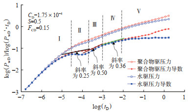
考虑诱导裂缝的聚合物驱垂直裂缝井典型试井曲线(图 6)存在5个流动段:纯井筒储存阶段(Ⅰ段),该阶段曲线主要受井筒储集系数影响,在双对数坐标中,无因次压力和压力导数曲线重合,呈现一条斜率为1.00的直线;双线性流阶段(Ⅱ段),为诱导裂缝内及裂缝周围流体的线性流,该阶段压力和压力导数曲线互相平行,压力导数曲线呈斜率为0.25的直线段;线性流阶段(Ⅲ段),即诱导裂缝内流体向地层的流动,压力导数曲线呈斜率为0.50的线性流阶段;椭圆流阶段(Ⅳ段),此阶段压力导数曲线呈斜率为0.36的直线;径向流阶段(Ⅴ段),压力波及范围逐渐扩大,水驱压力导数曲线呈水平直线段而聚合物驱则为一条上翘的曲线,这是由于聚合物在多孔介质内的剪切变稀作用,渗流阻力变化从而曲线上翘。本模型计算的聚合物驱垂直裂缝的压力动态特征曲线与徐有杰等[23]得出的特征曲线流动阶段及各阶段特征一致,说明了该方法正确可靠。
|
下载原图 图 6 考虑诱导裂缝的水驱和聚合物驱压力动态特征曲线对比 Fig. 6 Comparison of pressure dynamic characteristic curves between water flooding and polymer flooding considering induced fractures |
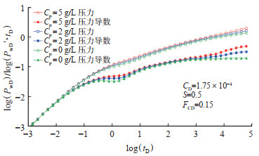
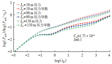
聚合物浓度的变化对试井压力产生影响,聚合物浓度越大其黏度越大,渗流阻力也越大(图 7)。从图中可看出,随着浓度增加,双线性流及非牛顿径向流阶段曲线均靠上;当聚合物注入质量浓度为0时,径向流阶段压力导数曲线呈水平直线段,与水驱现象一致。裂缝长度也会影响试井压力,随着裂缝半长的增加,双线性流持续时间变长(图 8)。
|
下载原图 图 7 受聚合物浓度影响的压力及压力导数动态曲线 Fig. 7 Influence of polymer concentration on pressure and pressure derivative dynamic curves |
|
下载原图 图 8 受裂缝长度影响的压力及压力导数动态曲线 Fig. 8 Influence of fracture length on pressure and pressure derivative dynamic curves |
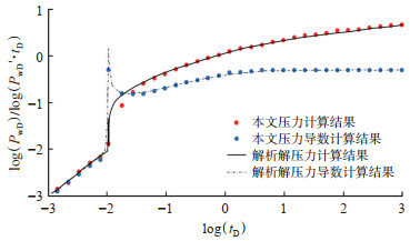
为验证方法的正确性,本次研究将聚合物设置为注入水,计算注水井关井后的裂缝闭合压力,并将压力动态曲线与Hoek[21]的参数解析解进行对比研究(图 9)。从图上可以看出,基于PEBI网格的考虑裂缝闭合的数值计算结果与Hoek[21]的参数解析解吻合良好。诱导裂缝闭合时,压力导数曲线出现一个突起的尖峰。
|
下载原图 图 9 考虑裂缝闭合的数值试井曲线与解析解对比 Fig. 9 Contrast of the numerical and analytical solution considering induced fracture closure |
将诱导裂缝闭合过程看作裂缝长度的变化,通过引入裂缝闭合速度因子(delpat)来控制裂缝闭合的快慢。诱导裂缝闭合使无因次压力及压力导数曲线迅速上升,压力导数曲线上升趋势更为显著,形成一个“尖峰”(图 10)。delpat越小,裂缝闭合越快,压力导数“尖峰”也就越明显。相反,delpat越大,裂缝闭合越慢,压力导数“尖峰”越不显著,曲线越靠右。delpat值的变化主要对后期拟径向流出现时间的早晚产生影响,聚合物驱与水驱诱导裂缝闭合的区别主要在裂缝闭合后,由于聚合物扩散及剪切稀化等流变特性使得其径向流阶段压力导数曲线上翘。
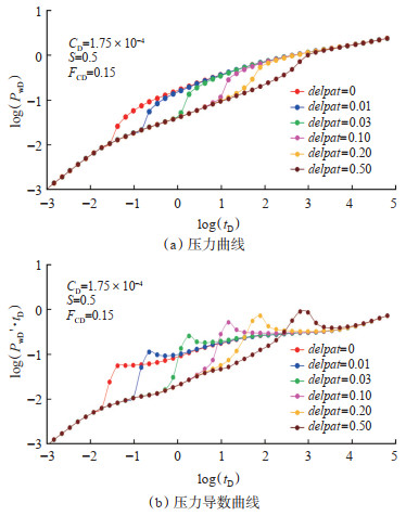
|
下载原图 图 10 受裂缝闭合速度影响的压力及压力导数动态曲线 |
(1)考虑诱导裂缝的注聚井压力动态曲线划分为5个流动段:纯井筒储存阶段,双线性流阶段,线性流阶段,椭圆流阶段,非牛顿径向流阶段。
(2)聚合物浓度主要影响试井压力变化的后期。曲线上表现为随着浓度增加,曲线上翘明显;裂缝半长越小,线性流阶段持续时间越短。
(3)注聚井关井测压时,裂缝闭合速度因子(delpat)越大,闭合越慢,压力导数曲线峰值越低,曲线越靠右,晚期拟径向流出现时间越晚。
| [1] |
金亚杰. 国外聚合物驱油技术研究及应用现状. 非常规油气, 2017, 4(1): 116-122. JIN Yajie. Progress in research and application of polymer flooding technology abroad. Journal of Unconventional Oil and Gas, 2017, 4(1): 116-122. DOI:10.3969/j.issn.2095-8471.2017.01.020 |
| [2] |
孙龙德, 伍晓林, 周万富, 等. 大庆油田化学驱提高采收率技术. 石油勘探与开发, 2018, 45(4): 636-645. SUN Longde, WU Xiaolin, ZHOU Wanfu, et al. Technologies of enhancing oil recovery by chemical flooding in Daqing Oilfield, NW China. Petroleum Exploration and Development, 2018, 45(4): 636-645. |
| [3] |
廖广志, 王强, 王红庄, 等. 化学驱开发现状与前景展望. 石油学报, 2017, 38(2): 196-207. LIAO Guangzhi, WANG Qiang, WANG Hongzhuang, et al. Chemical flooding development status and prospect. Acta Petrolei Sinica, 2017, 38(2): 196-207. |
| [4] |
韩培慧, 闫坤, 曹瑞波, 等. 聚驱后油层提高采收率驱油方法. 岩性油气藏, 2019, 31(2): 143-150. HAN Peihui, YAN Kun, CAO Ruibo, et al. Oil displacement methods for enhanced oil recovery after polymer flooding. Lithologic Reservoirs, 2019, 31(2): 143-150. |
| [5] |
ZHU Youyi. Current developments and remaining challenges of chemical flooding EOR techniques in China[R]. SPE 174566, 2015.
|
| [6] |
范天一, 宋新民, 吴淑红, 等. 低渗透油藏水驱动态裂缝数学模型及数值模拟. 石油勘探与开发, 2015, 42(4): 496-501. FAN Tianyi, SONG Xinmin, WU Shuhong, et al. A mathematical model and numerical simulation of waterflood induced dynamic fractures of low permeability reservoirs. Petroleum Exploration and Development, 2015, 42(4): 496-501. |
| [7] |
HAGOORT J. Waterflood-induced hydraulic fracturing[D]. Delft: Technical University of Delft, 1981.
|
| [8] |
KONING E J L. Waterflooding Under Fracturing Conditions[D]. Delft: Technical University of Delft, 1988.
|
| [9] |
VAN DEN HOEK P J. Pressure transient analysis in fractured produced water injection wells[R]. SPE 77946, 2002.
|
| [10] |
VAN DEN HOEK P J, AL-MASFRY R, ZWARTS D, et al. Waterflooding under dynamic induced fractures: Reservoir management and optimization of fractured waterfloods[R]. SPE 110379, 2008.
|
| [11] |
王友净, 宋新民, 田昌炳, 等. 动态裂缝是特低渗透油藏注水开发中出现的新的开发地质属性. 石油勘探与开发, 2015, 42(2): 222-228. WANG Youjing, SONG Xinmin, TIAN Changbing, et al. Dynamic fractures are an emerging new development geological attribute in water-flooding development of ultra-low permeability reservoirs. Petroleum Exploration and Development, 2015, 42(2): 222-228. |
| [12] |
汪洋, 程时清, 于海洋, 等. 考虑注水诱发微裂缝属性参数变化的注水井不稳定压力分析[C]. 中国力学大会-2017暨庆祝中国力学学会成立60周年大会论文集, 2017: 739-747. WANG Yang, CHENG Shiqing, YU Haiyang, et al. Semi-analytical modeling for water injection well in tight reservoir considering the variation of waterflood-induced fracture properties[C]. China Mechanical Assembly-Proceedings of the 60th Anniversary Conference of Chinese Society of Mechanics, 2017: 739-747. |
| [13] |
崔永正, 姜瑞忠, 郜益华, 等. 空间变导流能力压裂井CO2驱试井分析. 岩性油气藏, 2020, 32(4): 172-180. CUI Yongzheng, JIANG Ruizhong, GAO Yihua, et al. Pressure transient analysis of hydraulic fractured vertical wells with variable conductivity for CO2 flooding. Lithologic Reservoirs, 2020, 32(4): 172-180. |
| [14] |
曾杨, 康晓东, 唐恩高, 等. 三层油藏水驱后转聚驱的试井解释方法. 岩性油气藏, 2018, 30(5): 146-153. ZENG Yang, KANG Xiaodong, TANG Engao, et al. Well test analysis method for polymer flooding after water flooding in triplelayer reservoir. Lithologic Reservoirs, 2018, 30(5): 146-153. |
| [15] |
査文舒. 基于PEBI网格的油藏数值计算及其实现[D]. 合肥: 中国科学技术大学, 2009. ZHA Wenshu. Numerical reservoir calculation on PEBI grids and implementation[D]. Hefei: University of Science and Technology of China, 2009. |
| [16] |
贾智淳, 闫术, 董晓芳, 等. 剪切变稀作用对聚驱试井分析影响的数值研究. 西南石油大学学报(自然科学版), 2016, 38(5): 107-114. JIA Zhichun, YAN Shu, DONG Xiaofang, et al. Numerical study on the impact of shear thinning behavior in well test analysis for polymer flooding. Journal of Southwest Petroleum University (Science & Technology Edition), 2016, 38(5): 107-114. |
| [17] |
姜瑞忠, 花靖, 路淇安, 等. 基于浓度分布的聚合物驱流度控制方法. 长江大学学报(自然科学版), 2019, 16(9): 37-42. JIANG Ruizhong, HUA Jing, LU Qi'an, et al. Method for flow control in polymer flooding based on concentration distribution. Journal of Yangtze University(Natural Science Edition), 2019, 16(9): 37-42. DOI:10.3969/j.issn.1673-1409.2019.09.007 |
| [18] |
肖伟, 石成方, 王凤兰, 等. 聚合物驱油计算理论方法. 北京: 石油工业出版社, 2004. XIAO Wei, SHI Chengfang, WANG Fenglan, et al. Theoretical method of polymer flooding. Beijing: Petroleum Industry Press, 2004. |
| [19] |
YUAN Changli, DELSHAD M, WHEELER M. Modeling multiphase non-Newtonian polymer flow in IPARS parallel framework. Networks & Heterogeneous Media, 2010, 5(3): 583-602. DOI:10.3934/nhm.2010.5.583 |
| [20] |
DAM D B, PATEN C J, ROMIJN R. Analysis of hydraulic fracture closure in laboratory engineering, experiments. Production & Facilities, 2000, 15(3): 340-349. DOI:10.2118/47380-MS |
| [21] |
VAN DEN HOEK P J. Dimensions and degree of containment of waterflood-induced fractures from pressure-transient analysis. Reservoir Evaluation & Engineering, 2005, 8(5): 377-387. DOI:10.2118/84289-PA |
| [22] |
张阳, 任晓娟, 李展峰. 覆压对致密砂岩人工闭合裂缝渗透率的影响. 天然气勘探与开发, 2015, 38(2): 56-58. ZHANG Yang, REN Xiaojuan, LI Zhanfeng. Effect of overburden on permeability of artificially closed fractures in tight sandstone. Natural Gas Exploration and Development, 2015, 38(2): 56-58. DOI:10.3969/j.issn.1673-3177.2015.02.014 |
| [23] |
徐有杰, 刘启国, 王庆, 等. 聚合物驱有限导流压裂井压力动态特征分析. 油气井测试, 2019, 28(1): 7-13. XU Youjie, LIU Qiguo, WANG Qing, et al. Pressure behaviors of polymer flooding finite-conductivity fracturing wells. Well Testing, 2019, 28(1): 7-13. |
 2022, Vol. 34


