诸多学者针对探测半径进行了大量研究,但大多集中在均质储层,对于其他复杂储层如复合油藏、多重介质油藏则研究较少。如Muskat[1]、Tek等[2]、Hurst等[3]均针对均质油藏提出了探测半径的计算公式。Ishteiwy等[4]根据油藏泄油面积,得到了常用的均质油藏直井探测半径计算公式。刘能强[5]利用压力导数曲线得到均质油藏直井的2个探测半径计算公式。从井型角度来看,水平井的渗流方式与直井不同,直井探测半径的计算公式已不适用于水平井。因此,结合不同油藏特点、不同井型找到合适的探测半径计算方法是十分必要的。王新海等[6-7]建立了无限大地层单相渗流模型并得到非均质油藏直井的探测半径计算公式。崔迪生等[8]利用等效渗流阻力法,得出了径向复合非均质油藏探测半径的计算公式,但这种计算方法只适合于油藏渗透率发生变化的情况。李传亮等[9]通过近似处理得到了一个计算均质油藏探测半径的新公式。毛伟[10]推导出了从流量角度计算均质油藏探测半径的公式。任允鹏等[11]针对低渗油气藏提出一种新的计算泄流半径的计算公式。朱黎鹞等[12]通过将水平井转化为虚拟直井的方法,得到了水平井探测半径的计算公式。
虽然对探测半径的研究已有很多,并获得多种计算公式,但针对非均质油藏水平井探测半径的研究却较少。在现代油藏开发[13-16]过程中,水平井位于非均质油藏的情况大量存在[17-18],因此,拟针对非均质油藏水平井[19-20]探测半径进行深入研究,并推导出其计算公式。
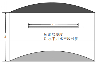
1 均质油藏探测半径 1.1 均质油藏水平井物理模型假设均质油藏水平井的基本物理模型[21-24]参数为:①油藏厚度为h,水平井水平段长度为L;②水平井单井以定产量生产;③油藏外边界可以是无穷边界;④原油和岩石微可压缩,恒压缩系数,原油黏度不变;⑤渗透率为常数;⑥等温达西渗流,忽略毛管压力和重力的影响(图 1)。位于油层中央的水平井垂向剖面详见图 2。

|
下载原图 图 1 均质油藏水平井俯视图 Fig. 1 Top view of horizontal well in a homogeneous reservoir |
|
下载原图 图 2 水平井垂向剖面 Fig. 2 Vertical profile of a horizontal well |
当水平井稳定渗流[25-26]时,在水平井的椭圆驱动面积内,水平剖面与垂向剖面组成了流体在地层中的渗流场(图 3、图 4)。

|
下载原图 图 3 水平井水平剖面渗流场分布 Fig. 3 Distribution of seepage field in a horizontal profile of horizontal well |
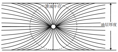
|
下载原图 图 4 水平井垂直剖面渗流场分布 Fig. 4 Distribution of seepage field in a vertical profile of horizontal well |
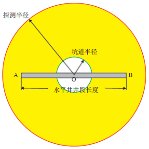
根据陈元千等[27]的思路,将以上水平井拟圆形生产坑道的外缘半径视为井筒半径,即可将水平井转化为虚拟直井(井筒半径为rpc)。基于以上认识和假设,将以水平井水平段AB的中点为圆心O,以拟圆形生产坑道的外缘半径为基准,压力波达到的最大位置至圆心O的距离定义为水平井的探测半径(图 5)[12, 28-29]。
|
下载原图 图 5 水平井探测半径示意图 Fig. 5 Schematic diagram of investigation radius of horizontal well |
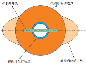
利用等产量原则[30],可将线性水平井段转化为拟圆形生产坑道(图 6),其坑道半径为
| $r_{\mathrm{pc}}=\frac{L}{C}$ | (1) |
|
下载原图 图 6 水平井拟圆形驱动边界及拟圆形生产坑道模型 Fig. 6 Model diagram of quasi circular drive boundary and quasi circular production tunnel of horizontal well |
式中:rpc为拟生产坑道半径,m;C为将水平井的线性井段转化为拟圆形生产坑道的转换常数;L为水平井井段长度,m。参考Joshi[31]的研究成果,C值可取值为4,即L/4的长度作为拟圆形生产坑道的半径
| $r_{\mathrm{pc}}=\frac{L}{4}$ | (2) |
在均质油藏中,储集层内的储层参数均相等,水平井位于均质油藏的模型可通过等阻力原理[20]简化为均质油藏中的大井径直井(图 6)。假设当生产时间(t)为0时,地层压力为pe,孔隙度为φe,液体密度为ρe;在给定t时刻时,地层压力、孔隙度和液体密度分别为p,φ和ρ(图 7)。

|
下载原图 图 7 微小圆环示意图(水平井在均质油藏取微环) Fig. 7 Schematic diagram of micro ring |
设定水平井以定产量q生产,即等效大口径直井以恒定产量生产。在垂直于直井的平面内,其渗流方式为平面径向流,油藏压力和径向坐标之间存在近似半对数关系。其地层压力可近似表示为
| $p(r, t)-C_1 \ln (r)+C_2, r_{\mathrm{pc}} \leqslant r \leqslant r_{\mathrm{inv}}(t)$ | (3) |
认为拟圆形生产坑道的压力始终等于井筒流动压力pwf(t),即
| $p\left(r_{\mathrm{pc}}\right)=p_{\mathrm{wf}}(t)$ | (4) |
压降漏斗前沿的地层压力始终等于初始地层压力,即
| $p\left[r_{\text {inv }}(t)\right]=p_i$ | (5) |
为了获得该地层的压力分布,将式(3)和式(5)联立,可得
| $p(r, t)=p_i-\frac{p_i-p_{\mathrm{wf}}(t)}{\ln \frac{r_{\mathrm{inv}}(t)}{r_{\mathrm{pc}}}} \ln \frac{r_{\mathrm{inv}}(t)}{r}, \quad r_{\mathrm{pc}} \leqslant r \leqslant r_{\mathrm{inv}}(t)$ | (6) |
式(3)—式(6)中:p(r,t)为径向半径为r时的储层压力,Pa;C1和C2为待定系数;r为压降区任意点的径向半径,m;pwf是井筒流动压力(即拟坑道处的压力),Pa;rinv(t)为当时间为t时的探测半径,m;pi为初始储层压力,Pa。
| $\rho={\rho}_0 e^{C_{\mathrm{L}}\left(p-p_0\right)}$ | (7) |
| $\varphi=\varphi_0 e^{C_{\mathrm{r}}\left(p-p_0\right)}$ | (8) |
式中:ρ为流体密度,kg/m3;φ为储层孔隙度,小数;CL为流体弹性压缩系数,Pa-1;Cr为岩石弹性压缩系数,Pa-1;ρ0,φ0和p0为对应变量的任意参考值。
将式(7)与式(8)相乘,可得
| ${\varphi} {\rho}={\varphi}_0 {\rho}_0 {e}^{\left(C_{\mathrm{r}}+C_{\mathrm{L}}\right)\left(p-p_0\right)}$ | (9) |
通过使用麦克劳林级数[32][式(2)—式(8)],将式(9)展开并忽略二阶和高阶项,可得
| $\varphi \rho=\varphi_0 \rho_0\left[1+C_{\mathrm{t}}\left(p-p_0\right)\right] $ | (10) |
| $C_{\mathrm{t}}=C_{\mathrm{L}}+C_{\mathrm{r}}$ | (11) |
微环柱体的体积近似计算公式为
| $V_{\text {inf }}=A_{\text {inf }} h=(2 \pi r \mathrm{d} r) h, r_{\mathrm{pc}} \leqslant r \leqslant r_{\text {inv }}(t)$ | (12) |
式中:Vinf为微环柱体的体积,m3;Ainf为微环柱体截面的面积,m2;h为储层厚度,m;Ct为油藏的综合弹性压缩系数,Pa-1。
在初始地层条件下,储存在径向无限小环孔隙中的流体质量可通过下式计算
| $m_{\mathrm{inf}-i}=V_{\mathrm{inf}} \varphi_i \rho_i=2 \pi r h \varphi_i \rho_i \mathrm{~d} r, r_{\mathrm{pc}} \leqslant r \leqslant r_{\mathrm{inv}}(t)$ | (13) |
式中:minf-i是初始地层条件下微环柱体中的初始流体质量,kg;φi是初始地层条件下的孔隙度,小数;ρi是初始油藏条件下的密度,kg/m3。
将式(10)代入式(13)中,则储存在径向无限小环孔隙中的流体质量可写为
| $\begin{gathered}m_{i n\text {f}-i}=(2 \pi r h \mathrm{d} r) \varphi_0 p_0\left[1+C_{\mathrm{t}}\left(p_i-p_0\right)\right], \\ \qquad r_{\mathrm{pc}} \leqslant r \leqslant r_{\mathrm{inv}}(t)\end{gathered}$ | (14) |
同样,当生产时间为t时,微环柱体中的剩余流体质量可通过以下公式计算,即
| $\begin{gathered}m_{in\text {f}}(t)=(2 \pi r h \mathrm{d} r) \varphi_0 p_0\left\{1+C_{\mathrm{t}}\left[p(r, t)-p_0\right]\right\}, \\ \qquad r_{\mathrm{pc}} \leqslant r \leqslant r_{\text {inv }}(t)\end{gathered}$ | (15) |
式中:minf(t)是生产时间为t时微环柱体中剩余的流体质量,kg。
根据质量守恒定律[33-35],初始流体质量减去剩余流体质量即微环柱体中流体质量的变化量,即
| $\begin{gathered}\Delta m_{in\text {f}}=m_{in\text {f}-i}-m_{in\text {f}}(t)=\left(2 \pi h \varphi_0 p_0 C_{\mathrm{t}}\right)\left[p_i-p(r, t)\right] r \mathrm{d} r, \\ \qquad r_{\mathrm{pc}} \leqslant r \leqslant r_{\mathrm{inv}}(t)\end{gathered}$ | (16) |
式中:Δminf是微环柱体中流体质量的变化量,kg。
因此,整个压降区内流体质量的总变化量可通过式(16)从拟坑道半径处到探测半径处的积分来计算,即
| $\begin{aligned} & \Delta m=\int_{r_{\mathrm{pc}}}^{r_{\mathrm{inv}}(t)}\left(\Delta m_{in\text {f}}\right) \mathrm{d} r= \\ & \qquad\qquad\left(2 \pi h \varphi_0 p_0 C_{\mathrm{t}}\right) \int_{r_{\mathrm{pc}}}^{r_{\text {inv }}(t)}\left[p_i-p(r, t)\right] r \mathrm{d} r\end{aligned}$ | (17) |
式中:Δm是该油藏在整个压降区域内流体质量的总变化量,kg。
将式(6)代入式(17)中,整个压降区域内流体质量的总变化量可表示为
| $\Delta m=\left(\pi h \varphi_0 p_0 C_{\mathrm{t}}\right) \frac{\left[p_i-p_{\mathrm{wf}}(t)\right]}{\ln \left[\frac{r_{\text {inv }}(t)}{r_{\mathrm{pc}}}\right]} \int_{r_{\mathrm{pc}}}^{r_{\text {inv }}(t)} 2 r \ln \left[\frac{r_{\text {inv }}(t)}{r}\right] \mathrm{d} r$ | (18) |
式中的积分项可由分部积分法计算得到,即
| $\begin{aligned} \int_{r_{\mathrm{pc}}}^{r_{\text {inv }}(t)} 2 r \ln \left[\frac{r_{\text {inv }}(t)}{r}\right] \mathrm{d} r= & {\left[r^2 \ln \frac{r_{\text {inv }}(t)}{r}\right]_{r_{\mathrm{pec}}}^{r_{\text {inv }}(t)}-} \\ & \int_{r_{\mathrm{pc}}}^{r_{\text {inv }}(t)} r^2\left[\ln \frac{r_{\text {inv }}(t)}{r}\right]^{\prime} \mathrm{d} r\end{aligned}$ | (19) |
式(19)等式右边第一项经整理后表示为
| $\left[r^2 \ln \frac{r_{\mathrm{inv}}(t)}{r}\right]_{r_{\mathrm{pc}}}^{r_{\mathrm{inv}}(t)}=-r_{\mathrm{pc}}^2 \ln \frac{r_{\mathrm{inv}}(t)}{r_{\mathrm{pc}}}$ | (20) |
等式右边第二项经整理后表示为
| $-\int_{r_{\mathrm{pc}}}^{r_{\mathrm{inv}}(t)} r^2\left[\ln \frac{r_{\mathrm{inv}}(t)}{r}\right]^{\prime} \mathrm{d} r=\int_{r_{\mathrm{pc}}}^{r_{\mathrm{inv}}(t)} r \mathrm{d} r=\frac{1}{2} r_{\mathrm{inv}}^2(t)-\frac{1}{2} r_{\mathrm{pc}}^2$ | (21) |
将式(20)和式(21)带入式(19)中,式(19)可化简为
| $\int_{r_{\mathrm{pc}}}^{r_{\mathrm{inv}}(t)} 2 r \ln \left[\frac{r_{\mathrm{inv}}(t)}{r}\right] \mathrm{d} r=\frac{1}{2} r_{\mathrm{inv}}^2(t)-r_{\mathrm{pc}}^2\left[\frac{1}{2}+\ln \frac{r_{\mathrm{inv}}(t)}{r_{\mathrm{pc}}}\right]$ | (22) |
将式(22)带入式(18)中,可得
| $\begin{aligned} \Delta m= & \left(\pi h \varphi_0 \rho_0 C_{\mathrm{t}}\right) \frac{\left[p_i-p_{\mathrm{wf}}(t)\right]}{\ln \left[\frac{r_{\mathrm{inv}}(t)}{r_{\mathrm{pc}}}\right]}\left\{\frac{1}{2} r_{\mathrm{inv}}^2(t)-\right. \\ & \left.r_{\mathrm{pc}}^2\left[\frac{1}{2}+\ln \frac{r_{\mathrm{inv}}(t)}{r_{\mathrm{pc}}}\right]\right\}\end{aligned}$ | (23) |
将式(23)中质量变化量Δm除以密度ρ0即可得到其体积的表达式
| $\begin{aligned} \Delta V= & \frac{\Delta m}{\rho_0}=\left(\pi h \varphi_0 C_{\mathrm{t}}\right) \frac{\left[p_i-p_{\mathrm{wf}}(t)\right]}{\ln \left[\frac{r_{\mathrm{inv}}(t)}{r_{\mathrm{pc}}}\right]}\left\{\frac{1}{2} r_{\text {inv }}^2(t)-\right. \\ & \left.r_{\mathrm{pc}}^2\left[\frac{1}{2}+\ln \frac{r_{\mathrm{inv}}(t)}{r_{\mathrm{pc}}}\right]\right\}\end{aligned}$ | (24) |
式中:ΔV是油藏压降漏斗区域中流体体积的变化量,即采出流体的体积,m3。
式(24)中的总体积变化等于油井产量的累积体积。由于油井是在以定产量q的恒定速度生产,设生产时间为t,可通过以下公式计算累积产量,即
| $\Delta V=q t$ | (25) |
联立式(22)和式(25),拟圆形坑道的产量可表示为
| $\begin{align} q= & \frac{\pi h \varphi_0 C_{\mathrm{t}}}{t} \frac{\left[p_i-p_{\mathrm{wf}}(t)\right]}{\ln \left[\frac{r_{\mathrm{inv}}(t)}{r_{\mathrm{pc}}}\right]}\left\{\frac{1}{2} r_{\mathrm{inv}}^2(t)-\right. \\ & \left.r_{\mathrm{pc}}^2\left[\frac{1}{2}+\ln \frac{r_{\mathrm{inv}}(t)}{r_{\mathrm{pc}}}\right]\right\}\end{align}$ | (26) |
鉴于此处渗流属于达西流[36],因此在距井半径为r处的产量可通过以下公式计算
| $q=A \cdot v=2 \pi r h \cdot\left(\frac{k}{\mu} \frac{\mathrm{d} p}{\mathrm{~d} r}\right), r_{\mathrm{pc}} \leqslant r \leqslant r_{\mathrm{inv}}(t)$ | (27) |
式中:A为流体流动的横截面面积,m2;v为流体的流速,m/s;k为油藏渗透率,mD;μ为油藏流体黏度,Pa·s。
为了方便后续积分,将式(27)变换为
| $q \frac{1}{r} d r=2 \pi \frac{k h}{\mu} \mathrm{d} p, r_{\mathrm{pc}} \leqslant r \leqslant r_{\mathrm{inv}}(t)$ | (28) |
将式(28)从拟坑道半径到压降漏斗的前沿进行积分,即
| $\int_{r_{\mathrm{pc}}}^{r_{\mathrm{inv}}(t)} q \frac{1}{r} \mathrm{~d} r=\int_{p_{\mathrm{wf}}}^{p_i} 2 \pi \frac{k h}{\mu} \mathrm{d} p$ | (29) |
通过积分运算,式(29)可转化为
| $q=\frac{2 \pi k h\left[p_i-p_{\mathrm{wf}}(t)\right]}{\mu \ln \left[\frac{r_{\mathrm{inv}}(t)}{r_{\mathrm{pc}}}\right]}$ | (30) |
联立式(26)与式(30),化简并进一步整理即可得到探测半径rinv(t)与生产时间t相关的方程
| $r_{\mathrm{inv}}^2(t)-2 r_{\mathrm{pc}}^2 \ln r_{\mathrm{inv}}(t)-r_{\mathrm{pc}}^2+2 r_{\mathrm{pc}}^2 \ln r_{\mathrm{pc}}=\frac{4 k}{\varphi_0 \mu C_{\mathrm{t}}} t$ | (31) |
由于φ0为一个任意的参考值,通常用孔隙度φ所取代,所以式(31)可写为
| $r_{\mathrm{inv}}^2(t)-2 r_{\mathrm{pc}}^2 \ln r_{\mathrm{inv}}(t)-r_{\mathrm{pc}}^2+2 r_{\mathrm{pc}}^2 \ln r_{\mathrm{pc}}=\frac{4 k}{\varphi \mu C_{\mathrm{t}}} t$ | (32) |
通过以上步骤得到的式(32)可用于计算水平井位于均质油藏的探测半径,即
| $r_{\mathrm{inv}}^2(t)-2 r_{\mathrm{pc}}^2 \ln r_{\mathrm{inv}}(t)-r_{\mathrm{pc}}^2+2 r_{\mathrm{pc}}^2 \ln r_{\mathrm{pc}}=4 \eta t$ | (33) |
| $\eta=\frac{k}{\varphi \mu C_{\mathrm{t}}}$ | (34) |
| $r_{\mathrm{pc}}=\frac{L}{4}$ | (35) |
式中:η为该油藏的导压系数,m2/s。
将式(35)代入式(33)中得探测半径的新公式
| $r_{\text {inv }}^2(t)-\frac{L}{8} \ln r_{\text {inv }}(t)-\frac{L^2}{16}+\frac{L^2}{8} \ln \frac{L}{4}=4 \eta t$ | (36) |
“坑道”假设条件下,模拟出来的渗流区域为圆形,这与通常情况下所理解的椭圆形有差异。为了避免这个差异,将圆形区域通过等面积的方法转换为椭圆形。无论是圆形渗流区还是椭圆形渗流区,二者的面积相等,即
| $S_{\mathrm{e}}=S_{\mathrm{r}}$ | (37) |
| $S_{\mathrm{e}}=\pi a b$ | (38) |
| $S_{\mathrm{r}}=\pi r_{\mathrm{inv}}^2$ | (39) |
式中:Se为椭圆形渗流区面积,m2;Sr为拟圆形渗流区面积,m2;a为椭圆形渗流区长半轴,m;b为椭圆形渗流区短半轴,m。
联立式(37)、式(38)、式(39),可得
| $r_{\mathrm{inv}}^2=a b$ | (40) |
椭圆的基本性质:长半轴平方等于短半轴平方与半焦距平方之和,即
| $a^2=b^2+c^2$ | (41) |
式中:c为半焦距,m。
根据椭圆渗流特征[37-39]可知椭圆形渗流的焦点为水平井的端点,即
| $c=\frac{L}{2}$ | (42) |
联立式(41)与式(42),可得
| $a^2=b^2+\frac{L^2}{4}$ | (43) |
联立式(40)与式(43),可得
| $4 a^4-a^2 L^2-4 r_{\text {inv }}^4=0$ | (44) |
| $r_{\mathrm{inv}}=\sqrt[4]{a^4-\frac{1}{4} a^2 L^2}$ | (45) |
或
| $4 b^4+b^2 L^2-4 r_{\text {inv }}^4=0$ | (46) |
| $r_{\mathrm{inv}}=\sqrt[4]{b^4+\frac{1}{4} b^2 L^2}$ | (47) |
将式(45)代入式(47)中,可得到水平井长半轴a(t)与生产时间t的方程
| $\begin{gathered}\sqrt{a^4(t)-\frac{1}{4} a^2(t) L^2}-\frac{L}{32} \ln \left[a^4(t)-\frac{1}{4} a^2(t) L^2\right]- \\ \frac{L^2}{16}+\frac{L^2}{8} \ln \frac{L}{4}=4 \eta t\end{gathered}$ | (48) |
将式(47)代入式(48)中,可得到水平井长半轴b(t)与生产时间t的方程
| $\begin{align}\sqrt{b^4(t)+\frac{1}{4} b^2(t) L^2} & -\frac{L}{32} \ln \left[b^4(t)+\frac{1}{4} b^2(t) L^2\right](t)- \\ & \frac{L^2}{16}+\frac{L^2}{8} \ln \frac{L}{4}=4 \eta t\end{align}$ | (49) |
式(48)与式(49)分别为长半轴a、短半轴b与生产时间t相关的非线性隐函数。若给定生产时间t,求解此方程可计算出椭圆形区域的长半轴a和短半轴b。
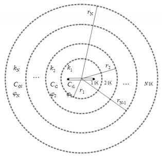
2 复合油藏水平井探测半径 2.1 复合油藏水平井物理模型复合油藏水平井物理模型[40]假设储层具有N个不同储层性质的径向区域,且水平井穿过这N个区域,但在每个区域中储层仍然被认为是均质的。从第1个区域到最后一个区域,分别被命名为“第1区域”、“第2区域”、……“第N区域”,相应的半径分别被标记为r1,r2,……,rN。因为最后一个区域(“Nth-zone”)的半径是储层的外部边界半径,所以rN通常被写成re(图 8)。当N=2时,该模型是最常见的2区复合模型,即内部区(第1区)和外部区(第2区)。对于N=3,模型变为3区复合模型,包括内部区(第1区)、中间区(第2区)和外部区(第3区)。
|
下载原图 图 8 水平井位于N区径向复合油藏模型 注:下标数字1,2,……,N是指不同储层属性参数如压力p、渗透率k、孔隙度φ以及岩石和流体的综合弹性压缩系数Ct在不同区域的不同表达。 Fig. 8 Model diagram of horizontal well located in radial composite reservoir in zone N |
根据“拟坑道”法[27]可将水平井转化为类似直井的“拟坑道”,水平井探测半径的计算公式可借助直井探测半径的计算公式获得。对于复合油藏水平井而言,可以参照均质水平井探测半径的推导过程进行推导其探测半径计算公式。
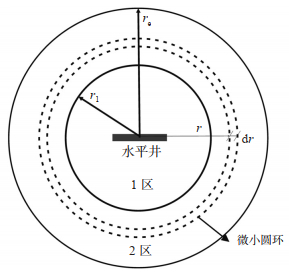
2.2.1 2区径向复合油藏水平井探测半径计算若2区径向复合油藏中以定产量q生产,压力波首先在内部区以第1区导压系数η1控制的速度传播,然后到达外部区并以第2区导压系数η2控制的另一速度在外部区传播(图 9)。在压力波到达内、外界面之前,其探测半径计算公式与均质油藏水平井的探测半径计算公式相同,可表示为
| $r_{\mathrm{inv}}^2(t)-2 r_{\mathrm{pc}}^2 \ln r_{\mathrm{inv}}(t)-r_{\mathrm{pc}}^2+2 r_{\mathrm{pc}}^2 \ln r_{\mathrm{pc}}=\frac{4 k_1}{\varphi_1 \mu_1 C_{\mathrm{t} 1}} t$ | (50) |
| $r_{\mathrm{pc}}=\frac{L}{4}$ | (51) |
| $r_{\text {inv }}^2(t)-\frac{L}{8} \ln r_{\text {inv }}(t)-\frac{L^2}{16}+\frac{L^2}{8} \ln \frac{L}{4}=4 \frac{4 \bar{k}}{\varphi \mu C_{\mathrm{t}}} t$ | (52) |
|
下载原图 图 9 2区复合油藏水平井模型取微小圆环示意图 Fig. 9 Schematic diagram of taking micro-ring in composite reservoir of horizontal well located in zone 2 |
式中:rinv(t)为当生产时间为t时的探测半径,m;t为生产时间,s;k1为径向复合油藏第1区储层的渗透率,mD;φ1为径向复合油藏第1区储层的孔隙度,小数;μ1为流体在第1区流动时的流体黏度,Pa·s;Ct1为径向复合油藏第1区储层的综合弹性压缩系数,Pa-1。
当压力波到达内区、外区界面后,需重新推导探测半径的计算公式。具体推导过程与均质油藏探测半径计算公式的推导方法类似。2区复合油藏中水平井探测半径的计算可分为2个部分:①压力波在第1区传播;②当压力波传播至第2区。当压力波仅在1区传播时,其水平井探测半径的计算公式与均质储层水平井探测半径的计算公式相同。
当压力波传播至2区时,其水平井探测半径的计算公式为
| $\begin{gathered}r_{\text {inv }}^2(t)-2 r_1^2 \ln r_{\text {inv }}(t)-r_1^2+2 r_1^2 \ln r_1= \\ \qquad \frac{4 k_2}{\varphi_2 \mu_2 C_{12}}\left(t-t_1\right)\end{gathered}$ | (53) |
| $\left\{\begin{array}{l}r_{\mathrm{pc}}=\frac{L}{4} \\ r_{\mathrm{inv}}^2(t)-2 r_{\mathrm{pc}}^2 \ln r_{\mathrm{inv}}(t)-r_{\mathrm{pc}}^2+2 r_{\mathrm{pc}}^2 \ln r_{\mathrm{pc}}=4 \eta_1 t, \left(r_{\mathrm{pc}}<r_{\mathrm{inv}} \leqslant r_1, t \leqslant t_1\right) \\ r_{\mathrm{inv}}^2(t)-2 r_1^2 \ln r_{\mathrm{inv}}(t)-r_1^2+2 r_1^2 \ln r_1=4 \eta_2\left(t-t_1\right), \left(r_{\mathrm{inv}}>r_1, t>t_1\right) \\ \eta_{\mathrm{j}}=\frac{k_{\mathrm{j}}}{\varphi_{\mathrm{j}} \mu_{\mathrm{j}} C_{\mathrm{tj}}}, \quad(j=1, 2) \\ t_1=\frac{r_1^2-2 r_{\mathrm{pc}}^2 \ln r_1-r_{\mathrm{pc}}^2+2 r_{\mathrm{pc}}^2 \ln r_{\mathrm{pc}}}{4 \eta_2}\end{array}\right.$ | (54) |
式中:ηj为径向复合油藏第j区的导压系数,m2/s;kj为径向复合油藏第j区的渗透率,m2;φj为径向复合油藏第j区的孔隙度,小数;μj为流体在径向复合油藏第j区流动时的黏度,Pa·s;rpc为拟生产坑道的半径,m。
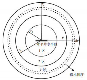
2.2.2 3区径向复合油藏水平井探测半径计算当压力波传播至第2区与第3区之间的界面后(图 10),需重新推导探测半径的计算公式。当N=3时,该径向复合储层是一个3区复合油藏,其探测半径的计算公式可表示为
| $\left\{\begin{array}{l}r_{\mathrm{pc}}=\frac{L}{4} \\ r_{\mathrm{inv}}^2(t)-2 r_{\mathrm{pc}}^2 \ln r_{\mathrm{inv}}(t)-r_{\mathrm{pc}}^2+2 r_{\mathrm{pc}}^2 \ln r_{\mathrm{pc}}=4 \eta_1 t, \quad\left(r_{\mathrm{pc}}<r_{\mathrm{inv}} \leqslant r_1, t \leqslant t_1\right) \\ r_{\mathrm{inv}}^2(t)-2 r_1^2 \ln r_{\mathrm{inv}}(t)-r_1^2+2 r_1^2 \ln r_1=4 \eta_2\left(t-t_1\right), \left(r_1<r_{\mathrm{inv}} \leqslant r_2, t_1<t \leqslant t_2\right) \\ r_{\mathrm{inv}}^2(t)-2 r_2^2 \ln r_{\mathrm{inv}}(t)-r_2^2+2 r_2^2 \ln r_2=4 \eta_3\left(t-t_2\right), \left(r_{\mathrm{inv}}>r_2, t>t_2\right) \\ \eta_{\mathrm{j}}=\frac{k_{\mathrm{j}}}{\varphi_{\mathrm{j}} \mu_{\mathrm{j}} C_{\mathrm{tj}}}, \quad(j=1, 2, 3) \\ t_1=\frac{r_1^2-2 r_{\mathrm{pc}}^2 \ln r_1-r_{\mathrm{pc}}^2+2 r_{\mathrm{pc}}^2 \ln r_{\mathrm{pc}}}{4 \eta_2} \\ t_2=\frac{t_1+\left(r_2^2-2 r_1^2 \ln r_2-r_1^2+2 r_1^2 \ln r_1\right)}{4 \eta_2}\end{array}\right.$ | (55) |
|
下载原图 图 10 水平井位于3区复合油藏取微小圆环示意图 Fig. 10 Schematic diagram of taking micro-ring in composite reservoir of horizontal well located in zone 3 |
式中:η1,η2,η3分别为径向复合油藏第1区、第2区、第3区的导压系数,m2/s;k1,k2,k3分别为径向复合油藏第1区、第2区、第3区的渗透率,mD;φ1,φ2,φ3分别为径向复合油藏第1区,第2区,第3区的孔隙度,小数;μ1,μ2,μ3分别为流体在复合油藏第1区,第2区,第3区流动时流体的黏度,Pa·s;Ctj为复合油藏第j区储层的综合弹性压缩系数,Pa-1;rj为径向复合油藏第j区的径向半径,m;tj为压力波到达径向第j区半径的时间,s;j代表径向复合油藏的区域号。
2.2.3 N区径向复合油藏水平井探测半径计算通过归纳总结水平井在均质油藏、2区复合油藏、3区复合油藏探测半径的计算公式,可得到N区径向复合油藏水平井探测半径的计算公式
| $\left\{ \begin{array}{l} {r_{{\rm{pc}}}} = \frac{L}{4}\\ r_{{\rm{inv}}}^2(t) - 2r_{{\rm{pc}}}^2\ln {r_{{\rm{inv}}}}(t) - r_{{\rm{pc}}}^2 + 2r_{{\rm{pc}}}^2\ln {r_{{\rm{pc}}}} = 4{\eta _1}t, \;\;\;{\kern 1pt} \left( {{r_{{\rm{pc}}}} < {r_{{\rm{inv}}}}{r_1}, t{t_1}} \right)\\ r_{{\rm{inv }}}^2(t) - 2r_1^2\ln {r_{{\rm{inv }}}}(t) - r_1^2 + 2r_1^2\ln {r_1} = 4{\eta _2}\left( {t - {t_1}} \right), \;\;\;{\kern 1pt} \left( {{r_1} < {r_{{\rm{inv }}}}{r_2}, {t_1} < t{t_2}} \right)\\ r_{{\rm{inv }}}^2(t) - 2r_2^2\ln {r_{{\rm{inv }}}}(t) - r_2^2 + 2r_2^2\ln {r_2} = 4{\eta _3}\left( {t - {t_2}} \right), \;\;\;{\kern 1pt} \left( {{r_{{\rm{inv }}}} > {r_2}, t > {t_2}} \right)\\ \;\;\;{\kern 1pt} \quad \;\;\;{\kern 1pt} \quad \;\;\;{\kern 1pt} \quad \;\;\;{\kern 1pt} \quad \;\;\;{\kern 1pt} \vdots \\ r_{{\rm{inv }}}^2(t) - 2r_{N - 2}^2\ln {r_{{\rm{inv }}}}(t) - r_{N - 2}^2 + 2r_{N - 2}^2\ln {r_{N - 2}} = 4{\eta _{N-1}}\left( {t - {t_{N - 2}}} \right), \left( {{r_{N - 2}} < {r_{{\rm{inv }}}}{r_{N-1}}, {t_{N - 2}} < t{t_{N-1}}} \right)\\ r_{{\rm{inv}}}^2(t) - 2r_{N-1}^2\ln {r_{{\rm{inv}}}}(t) - r_{N-1}^2 + 2r_{N-1}^2\ln {r_{N-1}} = 4{\eta _N}\left( {t - {t_{N-1}}} \right), \left( {{r_{{\rm{inv}}}} > {r_{N-1}}, t > {t_{N-1}}} \right)\\ {\eta _{\rm{j}}} = \frac{{{k_{\rm{j}}}}}{{{\varphi _{\rm{j}}}{\mu _{\rm{j}}}{C_{{\rm{tj}}}}}}, {t_1} = \frac{{r_1^2}}{{4{\eta _1}}}\qquad\qquad{\kern 1pt} (j = 1, 2, 3, \cdots , N)\\ {t_1} = \frac{{r_1^2 - 2r_{{\rm{pc}}}^2\ln {r_1} - r_{{\rm{pc}}}^2 + 2r_{{\rm{pc}}}^2\ln {r_{{\rm{pc}}}}}}{{4{\eta _2}}}, {t_2} = {t_1} + \frac{{r_2^2 - 2r_1^2\ln {r_2} - r_1^2 + 2r_1^2\ln {r_1}}}{{4{\eta _2}}}\\ {t_{\rm{k}}} = {t_{{\rm{k}} - 1}} + \frac{{r_{\rm{k}}^2 - 2r_{{\rm{k}} - 1}^2\ln {r_{\rm{k}}} - r_{{\rm{k}} - 1}^2 + 2r_{{\rm{k}} - 1}^2\ln {r_{{\rm{k}} - 1}}}}{{4{\eta _{\rm{k}}}}}, \;\;\;{\kern 1pt} (k = 2, 3, \cdots , N) \end{array} \right.$ | (56) |
该式表示探测半径与时间相关的非线性隐函数[41-42],均为非线性超越方程[43-45]。这些超越方程可通过迭代法(如牛顿迭代法)求解,进而求出径向复合多区油藏的探测半径。
3 实例应用与分析与直井探测半径不同,在0时刻的水平井探测半径不为0,而为拟生产坑道半径。这是因为本次计算探测半径的方法是运用“拟坑道”法,即假设水平井为拟生产坑道,因此水平井探测半径在0时刻时,其值为拟生产坑道半径。探测半径与该储层的导压系数密切相关,导压系数与储层渗透率成正比,与孔隙度和总可压缩性成反比,因此渗透率越大、孔隙度或综合弹性压缩系数越小,导压系数则越大。导压系数越大,压力波在储层中传播越快。
在生产时间相同的条件下,随着导压系数的增大,探测半径变大,探测半径典型特征曲线的位置会变高。对于复合油藏而言,每个区域的半径对探测半径的典型特征曲线也有较大影响。随着每个区域半径的增大,压力波对相应界面的响应会延迟,这使得曲线中相应的拐点会向右上方移动。
3.1 实例应用 3.1.1 均质油藏水平井探测半径实例应用X4井位于塔河油田,生产层系为三叠系,使用新推导出的均质油藏水平井探测半径公式计算水平井X4井的探测半径。根据X4井的基础数据和试井解释结果(表 1),利用式(37)计算水平井X5的探测半径。
|
|
下载CSV 表 1 塔河油田X4井基础数据和试井解释结果 Table 1 Basic Data and Well Test Interpretation Results of Well X4 in Taha Oilfield |
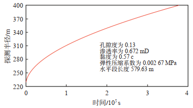
用牛顿迭代法求解超越方程,绘制了X4井压恢试井的探测半径与关井时间的关系曲线,如图 11所示。X4井最大关井时间为483.9 h(1 742 040 s)。因此,在压恢试井测试结束时,X4井的探测半径为341.73 m。
|
下载原图 图 11 塔里木盆地塔河油田X4井探测半径与关井时间的关系曲线 Fig. 11 Relation Curve between Investigation Radius and Shut-in Time of Well X4 in Tahe Oilfield, Tarim Basin |
X5井位于塔里木盆地阿克库勒隆起,该油藏为“断裂+构造”控制的复合岩性油藏,目的层为白垩系,根据X5井的基础数据和试井解释结果显示,该油藏为2区复合油藏(表 2)。利用式(54)计算水平井X5的探测半径。
|
|
下载CSV 表 2 塔里木盆地阿克库勒隆起X5井基础数据和试井解释结果 Table 2 Basic data and well test interpretation results of well X5 in Akekule uplift, Tarim Basin |
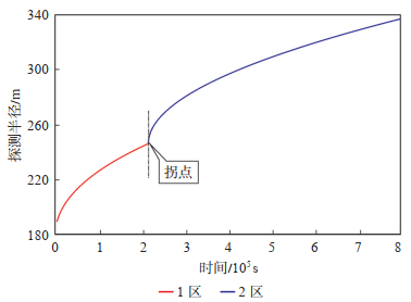
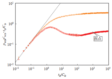
将数据代入式(54),可得X5井的拟圆形生产坑道的外缘半径rpc为194.91 m,η1为0.008 3 m2/s,η2为0.006 2 m2/s,r1为250 m,t1为214 950 s。使用牛顿迭代法求解可计算X5井的探测半径,并绘制X5井压恢试井的探测半径与关井时间的关系曲线(图 12)。X5井最大关井时间为183.5 h,因此,在压恢试井测试结束时,X5井的探测半径为327.65 m。同时,结合压恢试井双对数曲线(图 13),可发现曲线有一个“拐点”,该拐点为压力波到达内区边界的响应。
|
下载原图 图 12 塔里木盆地塔河油田X5井探测半径与关井时间的关系 水平井水平段长度779.63 m;1区半径为250 m;1区压缩系数为0.008 3 m/s;2区压缩系数为0.006 2 m2/s。 Fig. 12 Relation curve between investigation radius and shut-in time of well X5 in Tahe Oilfield, Tarim Basin |
|
下载原图 图 13 塔里木盆地塔河油田X5井压恢试井的无因次压力、压力导数和无因次时间双对数曲线 Fig. 13 Logarithmic curves of dimensionless pressure, pressure derivative and dimensionless time for pressure recovery well testing of well X5 in Tahe Oilfield, Tarim Basin |
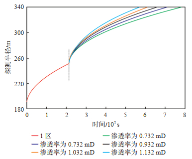
采取控制变量法,将复合油藏第2区的渗透率设置为0.732 mD,0.832 mD,0.932 mD,1.032 mD,1.132 mD。其他相关参数设置:1区储层平均渗透率为1.342 mD,平均孔隙度为0.11;2区储层平均孔隙度为0.08,流体黏度为0.88 mPa·s,综合弹性压缩系数为0.001 67 MPa-1,水平井长度为779.63 m(图 14)。
|
下载原图 图 14 受第2区渗透率影响的动态水平井探测半径典型曲线 Fig. 14 Typical curves of investigation radii of dynamic horizontal well affected by permeability of zone 2 |
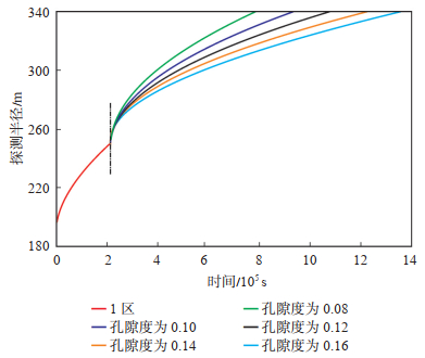
采用控制变量法,将第2区孔隙度的值分别设置为0.08,0.10,0.12,0.14和0.16。在探测半径的计算中,其他参数设置:1区储层平均渗透率为1.342 mD,平均孔隙度为0.11;2区储层平均渗透率为0.732 mD,流体黏度为0.88 mPa·s,综合弹性压缩系数为0.001 67 MPa-1,水平井长度为779.63 m(图 15)。
|
下载原图 图 15 受第2区孔隙度影响的动态水平井探测半径典型曲线 Fig. 15 Typical curves of investigation radii of dynamic horizontal well affected by porosity in zone 2 |
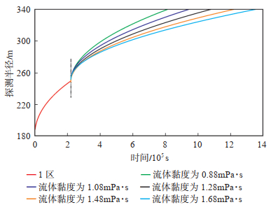
使用一组保持不变的储层参数k1=1.342 mD,k2=0.732 mD,φ1=0.11,φ1=0.08,Ct=0.001 67 MPa-1,μ1=0.88 mPa·s,r1=250 m,L=779.63 m,并设置第2区黏度分别为0.88 mPa·s,1.08 mPa·s,1.28 mPa·s,1.48 mPa·s和1.68 mPa·s模拟探测半径的典型特征曲线(图 16)。
|
下载原图 图 16 受第2区内流体黏度影响的动态水平井探测半径典型曲线 Fig. 16 Typical curves of investigation radii of dynamic horizontal well affected by fluid viscosity in zone 2 |
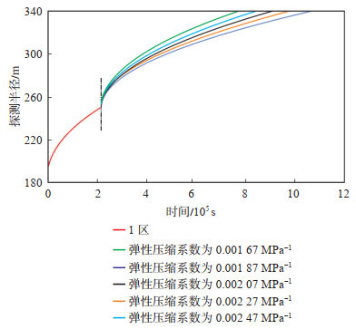
使用一组保持不变的储层参数k1=1.342 mD,k2=0.732 mD,φ1=0.11,φ2=0.08,Ct1=0.001 67 MPa-1,r1=250 m,μ1=0.88 mPa·s,L=779.63 m,并设置第2区储层综合弹性压缩系数分别为0.001 67 MPa-1,0.0018 7 MPa-1,0.002 07 MPa-1,0.002 27 MPa-1和0.002 47 MPa-1模拟探测半径的典型特征曲线(图 17)。
|
下载原图 图 17 受第2区综合弹性压缩系数影响的动态水平井探测半径典型曲线 Fig. 17 Typical curves of investigation radii of dynamic horizontal well affected by comprehensive elastic compression coefficient in zone 2 |
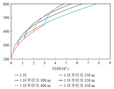
使用一组保持不变的储层参数k1=1.342 mD,k2=0.732 mD,φ1=0.11,φ2=0.08,μ=0.88 mPa·s,Ct=0.001 67 MPa-1,L=779.63 m,并设置第1区储层半径r1分别为250 m,300 m,350 m,400 m和450 m模拟探测半径的典型特征曲线(图 18)。
|
下载原图 图 18 受第1区半径影响的动态水平井探测半径典型曲线 Fig. 18 Typical curves of investigation radii of dynamic horizontal well affected by radius in zone 1 |
对于复合油藏而言,内区半径对探测半径的典型特征曲线也有很大影响。随着内区半径的增大,压力波对相应界面的响应会延迟,这使得曲线中相应的拐点向右上方移动。
综上所述,可以用相似的方法绘制出N区复合油藏探测半径随时间变化的典型特征曲线,并分析不同地层参数对探测半径典型特征曲线的影响。研究发现在一个N区复合油藏的典型特征曲线中出现了N-1个拐点,拐点代表压力波对2个相邻区域之间界面的响应。典型曲线可以通过N-1个拐点分成N个部分,每个区域的半径对探测半径的典型特征曲线将产生很大影响。随着每个区域半径的增大,压力波对相应界面的响应会延迟,这使得曲线中相应的拐点向右上方移动。
4 结论(1)均质油藏水平井、复合油藏水平井探测半径的计算公式在形式上表现为关于时间的非线性隐函数,须使用迭代法进行求解。
(2)油井探测半径随时间的增长而增大,储层特性参数对探测半径与时间的典型曲线具有明显影响,渗透率越大、孔隙度或总压缩系数越小,则典型曲线的位置越高。
(3)多区复合油藏水平井探测半径的典型曲线明显表现出复合油藏的多区特性,N区复合油藏的典型曲线上出现N-1个拐点,拐点代表压力波对相邻两带界面的响应,每个部分的曲线形状不同,分别代表相应的复合区域。区域复合半径的增加会使相应的拐点向右上角移动。
| [1] |
MUSKAT M. The flow of compressible fluids through porous media and some problems in heat conduction. Physics, 1934, 5(3): 71-94. DOI:10.1063/1.1745233 |
| [2] |
TEK M R, GROVE M L, POETTMANN F H. Method for predicting the back-pressure behavior of low permeability natural gas wells. Transactions of the AIME, 1957, 210(1): 302-309. DOI:10.2118/770-G |
| [3] |
HURST W, HAYNIE C K, WALKER R N, et al. Some problems in pressure build-up[C]. Dallas: Fall Meeting of the Society of Petroleum Engineers of AIME, 1996: 145.
|
| [4] |
ISHTEIWY A A, VAN POOLLEN H R. Radius of drainage and stabilization-time equations. Oil and Gas Journal, 1964, 62(4): 138-164. |
| [5] |
刘能强. 实用现代试井解释方法. 北京: 石油工业出版社, 2008. LIU Nengqiang. Practical modern well test interpretation method. Beijing: Petroleum Industry Press, 2008. |
| [6] |
WANG Xinhai, MA Shouxiang. Simple method for determination of radius of investigation for non-Newtonian fluids and other non-ideal systems[C]. Oklahoma: Proceedings of SPE Production Operations Symposium, 1997: 37410.
|
| [7] |
王新海, 夏位荣. 径向非均质地层调查半径与表皮系数. 大庆石油地质与开发, 1995, 14(3): 23-26. WANG Xinhai, XIA Weirong. Radius and skin factor of radial heterogeneous formation investigation. Petroleum Geology and Oilfield Development in Daqing, 1995, 14(3): 23-26. |
| [8] |
崔迪生, 贺子伦, 郭宝健, 等. 径向复合油藏探测半径计算方法. 油气井测试, 2005, 14(1): 15-16. CUI Disheng, HE Zilun, GUO Baojian, et al. Calculation method for investigation radius of radial composite reservoir. Well Testing, 2005, 14(1): 15-16. |
| [9] |
李传亮, 董利瑛. 油井探测半径的计算公式研究. 大庆石油地质与开发, 2002, 21(5): 32-33. LI Chuanliang, DONG Liying. Study on calculation formula of oil well investigation radius. Petroleum Geology & Oilfield Development in Daqing, 2002, 21(5): 32-33. |
| [10] |
毛伟. 基于流量的探测半径计算方法研究. 油气地质与采收率, 2006, 13(1): 77-78. MAO Wei. Research on calculation method of investigation radius based on flow. Petroleum Geology and Recovery Efficiency, 2006, 13(1): 77-78. |
| [11] |
任允鹏, 吴晓东, 王少军. 确定油气井泄流半径的新方法. 油气地质与采收率, 2010, 17(5): 73-75. REN Yunpeng, WU Xiaodong, WANG Shaojun. A New method for determining the discharge radius of oil and gas wells. Petroleum Geology and Recovery Efficiency, 2010, 17(5): 73-75. |
| [12] |
朱黎鹞, 童敏, 闫林. 水平井探测半径及其计算方法. 天然气工业, 2010, 30(5): 55-57. ZHU Liyao, TONG Min, YAN Lin. A horizontal well's investigation radius and its calculation methods. Natural Gas Industry, 2010, 30(5): 55-57. |
| [13] |
魏忠元, 张勇刚. 现代油藏描述技术的特点及发展动向. 特种油气藏, 2004, 11(5): 5-9. WEI Zhongyuan, ZHANG Yonggang. Characteristics and development trends of modern reservoir description technology. Special Oil & Gas Reservoirs, 2004, 11(5): 5-9. |
| [14] |
李涛. 现代试井技术在低渗透油藏高效开发中的应用. 云南化工, 2018, 45(4): 55-56. LI Tao. Application of modern well testing technology in efficient development of low-permeability oil reservoirs. Yunnan Chemical Industry, 2018, 45(4): 55-56. |
| [15] |
杨玉祥. 现代试井技术在低渗透油藏开发中的应用. 油气井测试, 2009, 18(3): 15-18. YANG Yuxiang. Application of modern well testing technology in development of low-permeability oil reservoirs. Well Testing, 2009, 18(3): 15-18. |
| [16] |
陈文龙, 吴迪, 尹显林, 等. 水平井在凝析气田开发中的应用及效果评价. 天然气地球科学, 2004, 15(3): 290-293. CHEN Wenlong, WU Di, YIN Xianlin, et al. Application and effect evaluation of horizontal wells in condensate gas field development. Natural Gas Geoscience, 2004, 15(3): 290-293. |
| [17] |
林承焰, 谭丽娟, 于翠玲. 论油气分布的不均一性(Ⅰ): 非均质控油理论的由来. 岩性油气藏, 2007, 19(2): 16-21. LIN Chengyan, TAN Lijuan, YU Cuiling. Research on the heterogeneous distribution of petroleum(Ⅰ). Lithologic Reservoirs, 2007, 19(2): 16-21. DOI:10.3969/j.issn.1673-8926.2007.02.003 |
| [18] |
林承焰, 谭丽娟, 于翠玲. 论油气分布的不均一性(Ⅱ): 非均质控油理论探讨. 岩性油气藏, 2007, 19(3): 14-22. LIN Chengyan, TAN Lijuan, YU Cuiling. Research on the heterogeneous distribution of petroleum(Ⅱ). Lithologic Reservoirs, 2007, 19(3): 14-22. DOI:10.3969/j.issn.1673-8926.2007.03.003 |
| [19] |
熊健, 李凌峰. 变形介质低渗透气藏水平井产能分析. 天然气与石油, 2011, 29(5): 50-52. XIONG Jian, LI Lingfeng. Analysis on horizontal well productivity in low permeability gas reservoirs with deformation medium. Natural Gas and Oil, 2011, 29(5): 50-52. |
| [20] |
徐有杰, 刘启国, 王瑞, 等. 复合油藏压裂水平井复杂裂缝分布压力动态特征. 岩性油气藏, 2019, 31(5): 161-168. XU Youjie, LIU Qiguo, WANG Rui, et al. Pressure transient of fractured horizontal well with complex fracture distribution in composite reservoir. Lithologic Reservoirs, 2019, 31(5): 161-168. DOI:10.12108/yxyqc.20190519 |
| [21] |
王怒涛, 李大凯, 张劲, 等. 均质油藏水平井试井解释图版绘制方法研究. 油气井测试, 2015, 24(5): 10-13. WANG Nuotao, LI Dakai, ZHANG Jin, et al. Research on drawing method of horizontal well test interpretation chart for homogeneous reservoir. Oil and Gas Well Testing, 2015, 24(5): 10-13. |
| [22] |
李顺初, 刘德华, 张普斋. 均质油藏在不同边界条件下的压力分布. 石油天然气学报, 2001, 23(2): 16-17. LI Shunchu, LIU Dehua, ZHANG Puzhai. Pressure distribution of homogeneous reservoirs under different boundary conditions. Acta Petrolei Sinica, 2001, 23(2): 16-17. |
| [23] |
尹洪军, 王洪涛, 付春权. 低渗透均质油藏地层压力的计算方法. 西部探矿工程, 2003, 15(10): 51-52. YIN Hongjun, WANG Hongtao, FU Chunquan. Calculation method of formation pressure in low-permeability homogeneous oil reservoirs. West-China Exploration Engineering, 2003, 15(10): 51-52. |
| [24] |
冉新权, 廖新维. 均质油藏试井资料极值拟合分析方法研究. 石油勘探与开发, 2000, 27(1): 67-68. RAN Xinquan, LIAO Xinwei. Study on extreme value fitting analysis method of well testing data in homogeneous reservoirs. Petroleum Exploration and Development, 2000, 27(1): 67-68. |
| [25] |
玄建. 水平井二维稳定渗流场分析及应用. 西南石油大学学报, 2018, 40(3): 115-120. XUAN Jian. Analysis and application of two-dimensional steady seepage field of horizontal well. Journal of Southwest Petroleum University, 2018, 40(3): 115-120. |
| [26] |
张强, 刘生国, 张俊松, 等. 考虑流体压缩性的应力敏感油藏水平井稳定渗流模型. 岩性油气藏, 2012, 24(4): 121-124. ZHANG Qiang, LIU Shengguo, ZHANG Junsong, et al. Horizontal well steady seepage model considering fluid compressibility in stress sensitive reservoir. Lithologic Reservoirs, 2012, 24(4): 121-124. |
| [27] |
陈元千. 水平井产量公式的推导与对比. 新疆石油地质, 2008, 29(1): 72-75. CHEN Yuanqian. Derivation and correlation of production rate formula for horizontal well. Xinjiang Petroleum Geology, 2008, 29(1): 72-75. |
| [28] |
李传亮. 油井探测半径的精确计算公式. 油气井测试, 2006, 15(3): 21-22. LI Chuanliang. The accurate calculation formula of well investigation radius. Oil and Gas Well Testing, 2006, 15(3): 21-22. |
| [29] |
GIGER F M, REISS L H, JOURDAN A P. The reservoir engineering aspects of horizontal drilling[C]. Houston: SPE Annual Technical Conference and Exhibition, 1984: 13024.
|
| [30] |
陈元千. 油气藏工程计算方法. 北京: 石油工业出版社, 1990: 138-151. CHEN Yuanqian. Calculation method of oil and gas reservoir engineering. Beijing: Petroleum Industry Press, 1990: 138-151. |
| [31] |
JOSHI S D. Augmentation of well productivity using slant and horizontal wells. Journal of Petroleum Technology, 1988, 40(6): 729-739. DOI:10.2118/15375-PA |
| [32] |
邢永丽, 陈建春. 泰勒级数在近似计算中的应用. 湘潭师范学院学报, 2004, 26(1): 5-8. XING Yongli, CHEN Jianchun. Application of Taylor series in approximate calculation. Journal of Xiangtan Normal University, 2004, 26(1): 5-8. |
| [33] |
李晓平, 赵必荣. 气水两相流井产能分析方法研究. 油气井测试, 2001, 10(4): 8-10. LI Xiaoping, ZHAO Birong. Study on well productivity analysis method of gas-water two-phase flow. Well Testing, 2001, 10(4): 8-10. |
| [34] |
张晶, 胡永乐, 冉启全, 等. 气藏水平井产能及水平段压力损失综合研究. 天然气地球科学, 2010, 21(1): 157-162. ZHANG Jing, HU Yongle, RAN Qiquan, et al. Comprehensive study on productivity of gas reservoir horizontal wells and pressure loss of horizontal sections. Natural Gas Geoscience, 2010, 21(1): 157-162. |
| [35] |
李元生, 李相方, 藤赛男, 等. 低渗透气藏产水气井两相产能方程研究. 特种油气藏, 2014, 21(4): 97-100. LI Yuansheng, LI Xiangfang, TENG Sainan, et al. Study on two-phase productivity equation of water-gas wells in low-permeability gas reservoirs. Special Oil & Gas Reservoirs, 2014, 21(4): 97-100. |
| [36] |
姚军, 孙海, 李爱芬, 等. 现代油气渗流力学体系及其发展趋势. 科学通报, 2018, 63(4): 425-451. YAO Jun, SUN Hai, LI Aifen, et al. Modern oil and gas seepage mechanics system and its development trend. Chinese Science Bulletin, 2018, 63(4): 425-451. |
| [37] |
张烈辉, 张苏, 熊燕莉, 等. 低渗透气藏水平井产能分析. 天然气工业, 2010, 30(1): 49-51. ZHANG Liehui, ZHANG Su, XIONG Yanli, et al. Productivity analysis of horizontal gas wells for low permeability gas reservoirs. Natural Gas Industry, 2010, 30(1): 49-51. |
| [38] |
李传亮, 朱苏阳, 柴改建, 等. 直井与水平井的产能对比. 岩性油气藏, 2018, 30(3): 12-16. LI Chuanliang, ZHU Suyang, CHAI Gaijian, et al. Comparison of productivity of vertical wells with horizontal wells. Lithologic Reservoirs, 2018, 30(3): 12-16. DOI:10.12108/yxyqc.20180302 |
| [39] |
李勇明, 吴磊, 陈希. 基于反常扩散模型的页岩气藏压裂水平井产能研究. 油气藏评价与开发, 2019, 9(1): 72-79. LI Yongming, WU Lei, CHEN Xi. Research on productivity of fractured horizontal wells in shale gas reservoirs based on anomalous diffusion model. Reservoir Evaluation and Development, 2019, 9(1): 72-79. |
| [40] |
贾永禄, 李允. 不等厚横向非均质复合油气藏试井分析模型及压力特征. 油气井测试, 1996, 5(3): 9-13. JIA Yonglu, LI Yun. Well testing analysis model and pressure characteristics of heterogeneous composite oil and gas reservoirs with unequal thickness in transverse direction. Well Testing, 1996, 5(3): 9-13. |
| [41] |
关江, 高启书, 孙淑艳. 确定隐函数中参数的最小二乘法. 齐齐哈尔大学学报, 2005, 21(1): 85-87. GUAN Jiang, GAO Qishu, SUN Shuyan. Least squares method for determining parameters in implicit functions. Journal of Qiqihar University, 2005, 21(1): 85-87. |
| [42] |
吴新元. 对牛顿迭代法的一个重要修改. 应用数学和力学, 1999, 20(8): 863-866. WU Xinyuan. An important modification to Newton's iterative method. Applied Mathematics and Mechanics, 1999, 20(8): 863-866. |
| [43] |
戴俭华, 滕德贵. 高次代数与超越方程组的对分区间套解法. 合肥工业大学学报, 1982, 7(4): 59-66. DAI Jianhua, TENG Degui. Interval nested solution method for high-order algebra and transcendental equation system. Journal of Hefei University of Technology, 1982, 7(4): 59-66. |
| [44] |
赵培玉, 吴素文, 冯大光, 等. 超越方程的数值计算方法与收敛速度分析. 长江大学学报, 2012, 9(5): 1-5. ZHAO Peiyu, WU Suwen, FENG Daguang, et al. Numerical calculation methods and convergence rates analysis of transcendental equations. Journal of Yangtze University, 2012, 9(5): 1-5. |
| [45] |
张安玲. 超越方程的优化解法. 数学的实践与认识, 2014, 44(22): 172-176. ZHANG Anling. Optimized solution methods for transcendental equations. Mathematics in Practice and Theory, 2014, 44(22): 172-176. |
 2024, Vol. 36


