2. 中国石油冀东油田公司 南堡油田作业区,河北 唐山 063005;
3. 中国石油大庆油田公司 第六采油厂,黑龙江 大庆 163114;
4. 北京大学 鄂尔多斯能源研究院,内蒙古 鄂尔多斯 017010
2. Nanpu Oilfield Operation Distric, PetroChina Jidong Oilfield Company, Tangshan 063005, Hebei, China;
3. No. 6 Oil Production Plant, PetroChina Daqing Oilfield Company, Daqing 163114, Heilongjiang, China;
4. Ordos Research Institute of Energy, Peking University, Ordos 017010, Inner Mongolia, China
随着致密油和页岩油的规模化开发,井网不断加密,水平井间距不断缩小[1-3]。在压裂过程中追求不断长缝长、小簇间距的同时会产生井间裂缝干扰的现象[4-6]。封猛等[7]利用微地震检测方法确定了压裂裂缝沟通干扰与压力波及干扰的井口压力特征,解决了不同井间干扰类型的分辨问题;李继庆等[8]建立了压裂裂缝、改造区和未改造区的三重区域耦合数学模型,采用PEBI网格和有限体积法进行了数值求解,分析了压裂段连通渗透率及激动量对干扰试井测试结果及压力场分布特征的影响;Molina等[9]基于三线性流模型建立了双井系统井间干扰模型,通过解析方法得到干扰条件下的地层压力,并利用数值模拟的计算结果与模型计算压力数据进行拟合得到不同干扰条件下的裂缝干扰系数,绘制了不同裂缝干扰及不同缝长的干扰系数图版;Yu等[10]建立了考虑储层和裂缝特性的复杂井间干扰系统关井压力变化的线性流模型,通过半解析求解方法,研究了人工主裂缝导流能力、裂缝干扰方式及基质渗透率对2口压裂水平井井底压力变化的影响。目前,关于裂缝干扰的研究主要集中在干扰的产生对产量及地层压力变化的影响[11-13],而对于裂缝干扰对水平井压力动态曲线特征的影响则研究较少。为此,建立考虑未改造区启动压力梯度的致密油水平井裂缝干扰渗流模型,通过引入半渗透边界条件及井间干扰系数α,研究裂缝连通干扰对致密油藏体积压裂水平井压力动态曲线及产能的影响,以期为致密油水平井开发提供参考。
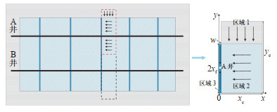
1 物理模型水平井通过体积压裂后会形成多条主裂缝和支裂缝[14-16],当2口水平井的主裂缝发生干扰时,裂缝互相连通(图 1)。根据三线性流模型的假设,选取2条裂缝间1/4的渗流区域进行分析,该模型将压裂水平井流动分为3个区域:区域1为未改造区;区域2为压裂改造区;区域3为水力裂缝区。根据每一区域储层及渗流特征,列出渗流方程,根据区域之间的压力与流量关系对渗流模型进行耦合求解。
|
下载原图 图 1 致密油藏压裂水平井渗流物理模型 Fig. 1 Physical model of fractured horizontal well seepage in tight reservoirs |
区域1为致密低渗透区域,流体在渗流过程中具有明显的低速非达西渗流特征,采用考虑启动压力梯度的线性流来描述该区域的渗流过程[17-19],假设在区域1内,考虑基质向微裂缝中的窜流为拟稳态窜流,拉式空间中的渗流数学模型为
| $ \left\{\begin{array}{l} \frac{\partial^2 \bar{p}_{1 \mathrm{D}}}{\partial y_{\mathrm{D}}^2}-G_{\mathrm{D}} \frac{\partial \bar{p}_{1 \mathrm{D}}}{\partial y_{\mathrm{D}}}-u_1 \bar{p}_{1 \mathrm{D}}=0 \\ \left.\frac{\partial \bar{p}_{1 \mathrm{D}}}{\partial y_{\mathrm{D}}}\right|_{y_{\mathrm{D}}=y_{\mathrm{eD}}}=0 \\ \left.\bar{p}_{1 \mathrm{D}}\right|_{y_{\mathrm{D}=1}}=\left.\bar{p}_{2 \mathrm{D}}\right|_{y_{\mathrm{D}=1}} \end{array}\right. $ | (1) |
其中:
式中:ω1为未改造区弹性储容比;λ1为未改造区窜流系数;η1D为区域1无因次导压系数;GD为无因次启动压力梯度;p1D为区域1无因次压力;yD为y方向无因次距离;xf为裂缝半长,m;yeD为区域1外边界无因次长度;pD为无因次压力;pi为原始地层压力,MPa;p为未改造区地层压力,MPa;K2为改造区渗透率,mD;h2为改造区油层厚度,m;qt为裂缝流量,m3/d;μ为流体黏度,mPa·s,B为原油体积系数。
2.1.2 改造区区域2为压裂改造区,使用双重介质模型进行表征,基质向微裂缝中的窜流为拟稳态窜流,2条相邻主裂缝间距的1/2处为不渗透边界层,考虑主裂缝表皮效应的影响,该区域拉式空间数学模型为
| $ \left\{\begin{array}{l} \frac{\partial^2 \bar{p}_{2 \mathrm{D}}}{\partial x_{\mathrm{D}}^2}+\frac{K_1}{K_2}\left(\frac{\partial \bar{p}_{1 \mathrm{D}}}{\partial y_{\mathrm{D}}}\right)_{y_{\mathrm{D}}=1}-u_2 \bar{p}_{2 \mathrm{D}}=0 \\ \left.\frac{\partial \bar{p}_{2 \mathrm{D}}}{\partial x_{\mathrm{D}}}\right|_{x_{\mathrm{D}}=x_{\mathrm{eD}}}=0 \\ \left.\bar{p}_{3 \mathrm{D}}\right|_{x_{\mathrm{D}}=\frac{w_{\mathrm{D}}}{2}}=\left.\left(\bar{p}_{2 \mathrm{D}}-S_{\mathrm{f}} \frac{\partial \bar{\rho}_{2 \mathrm{D}}}{\partial x_{\mathrm{D}}}\right)\right|_{x_{x_{\mathrm{D}}}=\frac{w_{\mathrm{D}}}{2}} \end{array}\right. $ | (2) |
其中:
式中:ω2为未改造区弹性储容比;λ2未改造区窜流系数;p2D为区域2无因次压力;p3D为区域3无因次压力;xD为x方向无因次距离;xeD为相邻主裂缝间不渗透边界的无因次长度;K1为未改造区渗透率,mD;Sf为主裂缝表皮系数。
2.1.3 裂缝区考虑主裂缝连通出现井间干扰,流体沿着主裂缝向A井和B井井底渗流的拉式空间数学模型分别
| $ \left\{\begin{array}{l} \frac{\partial^2 \bar{p}_{3 \mathrm{D}}}{\partial y_{\mathrm{D}}^2}+\left.\frac{2}{F_{\mathrm{CD}, \mathrm{A}}} \frac{\partial \bar{p}_{2 \mathrm{D}}}{\partial x_{\mathrm{D}}}\right|_{x_{\mathrm{D}}=\frac{w_{\mathrm{D}}}{2}}-\frac{s}{\eta_{3 \mathrm{D}}} \bar{p}_{3 \mathrm{D}}=0 \\ \left.\frac{\partial \bar{p}_{3 \mathrm{D}}}{\partial y_{\mathrm{D}}}\right|_{y_{\mathrm{D}}=1}=\frac{2 {\rm{ \mathsf{ π} }}}{s F_{\mathrm{CD}, \mathrm{A}}} q_{\mathrm{AD}} \\ \left.\frac{d \bar{p}_{\mathrm{fD}, \mathrm{A}}}{d y_{\mathrm{D}}}\right|_{y_{\mathrm{D}}=0}=\alpha\left(\left.\bar{p}_{\mathrm{fD}, \mathrm{A}}\right|_{y_{\mathrm{D}}=0}-\left.\bar{p}_{\mathrm{fD}, \mathrm{B}}\right|_{y_{\mathrm{D}}=0}\right) \end{array}\right. $ | (3) |
| $ \left\{\begin{array}{l} \frac{\partial^2 \bar{p}_{3 \mathrm{D}}}{\partial y_{\mathrm{D}}^2}+\left.\frac{2}{F_{\mathrm{CD}, \mathrm{B}}} \frac{\partial \bar{p}_{2 \mathrm{D}}}{\partial x_{\mathrm{D}}}\right|_{x_{\mathrm{D}}=\frac{w_{\mathrm{D}}}{2}}-\frac{s}{\eta_{3 \mathrm{D}}} \bar{p}_{3 \mathrm{D}}=0 \\ \left.\frac{\partial \bar{p}_{3 \mathrm{D}}}{\partial y_{\mathrm{D}}}\right|_{y_{\mathrm{D}}=-x_{\mathrm{FD}, \mathrm{B}}}=-\frac{2 {\rm{ \mathsf{ π} }}}{s F_{\mathrm{CD}, \mathrm{A}}} q_{\mathrm{BD}} \\ \left.\frac{d \bar{p}_{\mathrm{fD}, \mathrm{A}}}{d y_{\mathrm{D}}}\right|_{y_{\mathrm{D}}=0}=\alpha\left(\left.\bar{p}_{\mathrm{fD}, \mathrm{A}}\right|_{y_{\mathrm{D}}=0}-\left.\bar{p}_{\mathrm{fD}, \mathrm{B}}\right|_{y_{\mathrm{D}}=0}\right) \end{array}\right. $ | (4) |
其中:
式中:η3D为主裂缝无因次导压系数;FCD为无因次裂缝导流能力;wD为无因次裂缝宽度。
在干扰模型的建立和分析中,2口水平井通过裂缝尖端连通进行井间干扰,为此,在裂缝尖端使用第三类边界条件,即半渗透边界条件[9]:
| $ \left.\frac{d \bar{p}_{\mathrm{fD}, \mathrm{A}}}{d y_{\mathrm{D}}}\right|_{y_{\mathrm{D}}=0}=\alpha\left(\left.\bar{p}_{\mathrm{fD}, \mathrm{A}}\right|_{y_{\mathrm{D}}=0}-\left.\bar{p}_{\mathrm{fD}, \mathrm{B}}\right|_{y_{\mathrm{D}}=0}\right) $ | (5) |
式中:α为井间干扰系数,表示裂缝干扰程度的大小,其受水平井裂缝连通条数、裂缝半长和裂缝导流能力影响,α值越大,干扰程度越大,本文主要通过裂缝连通条数不同来讨论干扰系数的变化。当| α | > 0时,根据流量连续的条件,在此时使用达西定律,得出
| $ \left.\frac{d \bar{p}_{\mathrm{fD}, \mathrm{A}}}{d y_{\mathrm{D}}}\right|_{y_{\mathrm{D}}=0}=\left.K_{\mathrm{fD}} \frac{d \bar{p}_{\mathrm{fD}, \mathrm{B}}}{d y_{\mathrm{D}}}\right|_{y_{\mathrm{D}}=0} $ | (6) |
式中:
当α > 0时,流体通过裂缝从A井流入B井;当α<0时,表示流体从B井通过裂缝流入A井。在此我们选取α>0,即B井产量大于A井的情况进行讨论。
2.2 井底压力解由未改造区渗流方程组可求得
| $ \bar{p}_{1 \mathrm{D}}=\frac{\left(-\frac{r_2}{r_1}\right) \mathrm{e}^{r_1\left(y_{\mathrm{D}}-y_{\mathrm{eD}}\right)}+\mathrm{e}^{r_2\left(1-y_{\mathrm{eD}}\right)}}{\left(-\frac{r_2}{r_1}\right) \mathrm{e}^{r_1\left(1-y_{\mathrm{eD}}\right)}+\mathrm{e}^{r_2\left(1-y_{\mathrm{eD}}\right)}}\left. \bar{p}_{2 \mathrm{D}}\right|_{y_{\mathrm{D}}=1} $ | (7) |
其中:
由区域2的渗流方程组可求得其无因次压力表达式为
| $ \bar{p}_{2 \mathrm{D}}=\frac{\left.\cosh \left[\sqrt{\alpha_0}\left(x_{\mathrm{D}}-x_{\mathrm{eD}}\right)\right] \bar{p}_{3 \mathrm{D}}\right|_{x_{\mathrm{D}}=\frac{w_{\mathrm{D}}}{2}}}{\cosh \left[\sqrt{\alpha_0}\left(\frac{w_{\mathrm{D}}}{2}-x_{\mathrm{eD}}\right)\right]-S_{\mathrm{f}} \sqrt{\alpha_0} \sinh \left[\sqrt{\alpha_0}\left(\frac{w_{\mathrm{D}}}{2}-x_{\mathrm{eD}}\right)\right]} $ | (8) |
其中:
将改造区的无因次压力表达式代入到区域3的渗流方程中,结合边界条件可求得在拉式空间内的无因次A井裂缝尖端压力为
| $ \left.\bar{p}_{\mathrm{fD}, \mathrm{A}}\right|_{y_{\mathrm{D}}=0}=\bar{p}_{\mathrm{wD}, \mathrm{A}} \cosh \left[\sqrt{\beta_{\mathrm{A}}}\right]-\left(\frac{2 {\rm{ \mathsf{ π} }} q_{\mathrm{AD}}}{F_{\mathrm{CD}, \mathrm{A}}}\right) \frac{\sinh \sqrt{\beta_{\mathrm{A}}}}{s \sqrt{\beta_{\mathrm{A}}}} $ | (9) |
其中:
此时裂缝尖端的压力梯度为
| $ \begin{gathered} \left.\frac{\partial \bar{p}_{\mathrm{fD}, \mathrm{A}}}{\partial y_{\mathrm{D}}}\right|_{y_{\mathrm{D}}=0}=-\bar{p}_{\mathrm{wD}, \mathrm{A}} \sqrt{\beta_{\mathrm{A}}} \sinh \left[\sqrt{\beta_{\mathrm{A}}}\right]+ \\ \left(\frac{2 {\rm{ \mathsf{ π} }} q_{\mathrm{BD}}}{s F_{\mathrm{CD}, \mathrm{A}}}\right) \cosh \sqrt{\beta_{\mathrm{A}}} \end{gathered} $ | (10) |
同理可求得B井裂缝尖端压力和压力梯度分别为
| $ \begin{aligned} \left.\bar{p}_{\mathrm{fD}, \mathrm{B}}\right|_{y_{\mathrm{D}}=0}= & \bar{p}_{\mathrm{wD}, \mathrm{B}} \cosh x_{\mathrm{fD}, \mathrm{B}} \sqrt{\beta_{\mathrm{B}}}- \\ & \left(\frac{2 {\rm{ \mathsf{ π} }} q_{\mathrm{BD}}}{F_{\mathrm{CD}, \mathrm{A}}}\right) \frac{\sinh x_{\mathrm{fD}, \mathrm{B}} \sqrt{\beta_{\mathrm{B}}}}{s \sqrt{\beta_{\mathrm{B}}}} \end{aligned} $ | (11) |
| $ \begin{aligned} \left.\frac{\partial \bar{p}_{\mathrm{fD}, \mathrm{B}}}{\partial y_{\mathrm{D}}}\right|_{y_{\mathrm{D}}=0}= & -\bar{p}_{\mathrm{wD}, \mathrm{B}} \sqrt{\beta_{\mathrm{B}}} \sinh x_{\mathrm{fD}, \mathrm{B}} \sqrt{\beta_{\mathrm{B}}}- \\ & \left(\frac{2 {\rm{ \mathsf{ π} }} q_{\mathrm{BD}}}{s F_{\mathrm{CD}, \mathrm{A}}}\right) \cosh x_{\mathrm{fD}, \mathrm{B}} \sqrt{\beta_{\mathrm{B}}} \end{aligned} $ | (12) |
为了得到A井和B井的井底压力解析解,将压力和流量方程代入半渗透边界条件,可得到2个具有相同未知数的线性方程:
| $ \begin{gathered} -\bar{p}_{\mathrm{wD}, \mathrm{A}} \sqrt{\beta_{\mathrm{A}}} \sinh \sqrt{\beta_{\mathrm{A}}}+\left(\frac{2 {\rm{ \mathsf{ π} }} q_{\mathrm{AD}}}{s F_{\mathrm{CD}, \mathrm{A}}}\right) \cosh \sqrt{\beta_{\mathrm{A}}}= \\ \alpha\left[\bar{p}_{\mathrm{wD}, \mathrm{A}} \cosh \sqrt{\beta_{\mathrm{A}}}-\bar{p}_{\mathrm{wD}, \mathrm{B}} \cosh x_{\mathrm{fD}, \mathrm{B}} \sqrt{\beta_{\mathrm{B}}}-\frac{2 {\rm{ \mathsf{ π} }}}{s F_{\mathrm{CD}, \mathrm{A}}}\left(q_{\mathrm{AD}} \frac{\sinh \sqrt{\beta_{\mathrm{A}}}}{\sqrt{\beta_{\mathrm{A}}}}-q_{\mathrm{BD}} \frac{\sinh x_{\mathrm{fD}, \mathrm{B}} \sqrt{\beta_{\mathrm{B}}}}{\sqrt{\beta_{\mathrm{B}}}}\right)\right] \end{gathered} $ | (13) |
| $ \bar{p}_{\mathrm{wD}, \mathrm{A}} \sqrt{\beta_{\mathrm{A}}} \sinh \sqrt{\beta_{\mathrm{A}}}+k_{\mathrm{fD}} \bar{p}_{\mathrm{wD}, \mathrm{B}} \sqrt{\beta_{\mathrm{B}}} \sinh x_{\mathrm{fD}, \mathrm{B}} \sqrt{\beta_{\mathrm{B}}}=\left(\frac{2 {\rm{ \mathsf{ π} }}}{s F_{\mathrm{CD}, \mathrm{A}}}\right)\left(q_{\mathrm{AD}} \cosh \sqrt{\beta_{\mathrm{A}}}+k_{\mathrm{fD}} q_{\mathrm{BD}} \cosh x_{\mathrm{fD}, \mathrm{B}} \sqrt{\beta_{\mathrm{B}}}\right) $ | (14) |
因此,可以求得两干扰井井底压力解分别为
| $ \bar{p}_{\mathrm{wD}, \mathrm{A}}=\frac{2 {\rm{ \mathsf{ π} }}}{F_{\mathrm{CD}, \mathrm{A}}}\left(\frac{1}{s \sqrt{\beta_{\mathrm{A}}}} \cdot \frac{f_1+f_2+f_3}{f_4+f_5+f_6}\right) $ | (15) |
其中:
| $ \bar{p}_{\mathrm{wD}, \mathrm{B}}=\frac{2 {\rm{ \mathsf{ π} }}}{F_{\mathrm{CD}, \mathrm{A}}}\left(\frac{1}{s \sqrt{\beta_{\mathrm{B}}}} \cdot \frac{g_1+g_2+g_3+g_4}{g_5+g_6+g_7}\right) $ | (16) |
其中:
根据拉式空间中定生产压力的无因次产量解与定产量生产的无因次井底压力解之间有如下的关系式[20]:
| $ \bar{q}_{\mathrm{D}}=\frac{1}{s^2 \bar{p}_{\mathrm{wD}}} $ | (17) |
将式(15)和式(16)的井底压力解代入式(17),可得到定生产压力条件下的A井和B井的无因次产量和,再通过Stehfest数值反演[21]计算实空间的井底压力、压力导数和无因次产量。
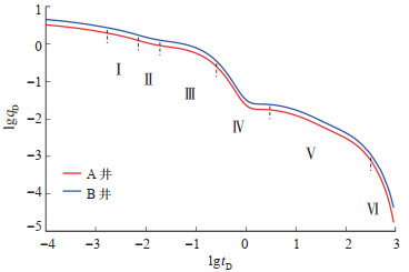
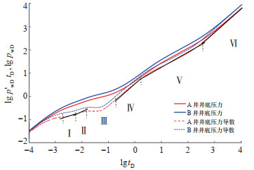
3 结果与分析基于上述数学模型,对影响井底压力和产量的井间干扰系数、启动压力梯度、裂缝导流能力等因素进行分析。根据表 1给出的模拟计算参数,绘制了无干扰条件下A井、B井的产量递减曲线和井底压力试井曲线(图 2、图 3)。
|
|
下载CSV 表 1 试井解释参数 Table 1 Well test interpretation parameters |
|
下载原图 图 2 无干扰条件下产量递减曲线(α= 0,GD= 0.1) Ⅰ.主裂缝与改造区双线性流阶段;Ⅱ.改造区线性流阶段;Ⅲ.改造区窜流阶段;Ⅳ. 改造区拟稳定流阶段;Ⅴ. 未改造区线性流阶段;Ⅵ.未改造区边界反映阶段。 Fig. 2 Production decline curves without interference |
|
下载原图 图 3 无干扰条件下井底压力和压力导数曲线(α = 0,GD= 0.1) Ⅰ.主裂缝与改造区双线性流阶段;Ⅱ.改造区线性流阶段;Ⅲ.改造区窜流阶段;Ⅳ.改造区拟稳定流阶段;Ⅴ.未改造区线性流阶段;Ⅵ.未改造区边界反映阶段。 Fig. 3 Bottom hole pressure and pressure derivative curves without interference |
由图 2、图 3可看出,在B井产量高于A井产量的定产条件下,B井压差大。B井的Ⅰ,Ⅱ,Ⅲ及Ⅳ等阶段的发生都略早于A井对应的各个流动阶段。
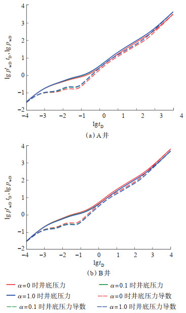
3.1 井底压力特征 3.1.1 井间干扰系数由图 4可看出,随着井间干扰系数α的增大,A井的井底压力和压力导数也有所增大,α越大,井底压力越大,相应的压力导数也就越大;B井无因次井底压力和压力导数随之减小,这一情况在早期较为明显。
|
下载原图 图 4 井间干扰系数对水平井井底压力与压力导数的影响(GD= 0.1,FCDA = FCDB = 20.0) Fig. 4 Effect of interwell interference coefficient on bottom hole pressure and pressure derivative of horizontal wells |
由图 4a可看出,裂缝干扰与不发生干扰相比,A井井点的压力及压力导数曲线会出现全阶段的上移。由于A井产量小,发生裂缝干扰时,A井连通裂缝中的流体通过裂缝流向B井。裂缝连通数量越多,A井维持定产条件需要消耗的压差越大,相应的无因次压力曲线上移。井间干扰系数大小引起的无因次压力变化主要发生在流动早期,此时流体流动主要发生在主裂缝和改造区范围。裂缝连通越多,两井通过裂缝流体交换越显著,压力传播较快,改造区线性流持续的时间越长,改造区窜流发生得越晚,同时改造区拟稳定流就发生得越晚。图 4b中B井压力和压力导数变化规律与之相反。
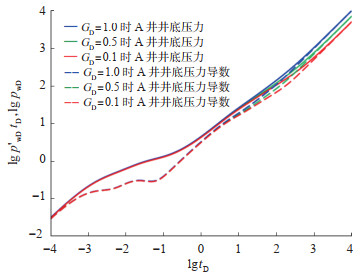
3.1.2 启动压力梯度图 5是未改造区无因次启动压力梯度分别取0.1,0.5,1.0时A井的压力动态曲线。从图 5中可看出,启动压力梯度主要影响未改造区试井曲线的形态,启动压力梯度越大,渗流阻力就越大,压力动态曲线上移,同时可以发现,启动压力梯度越大,拟稳定流发生的时间就越早。
|
下载原图 图 5 启动压力梯度对水平井井底压力和压力导数的影响(α = 0.1,FCDA = FCDB = 20.0) Fig. 5 Effect of threshold pressure pradient on bottom hole pressure and pressure derivative of horizontal wells |
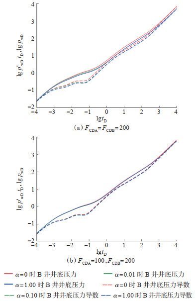
裂缝导流能力决定了主裂缝与改造区双线性流出现时间的早晚。随裂缝导流能力增大,井筒储集效应的影响减小,续流过渡段结束的时间越早,主裂缝与改造区双线性流出现得越早,持续的时间越长。当裂缝导流能力较小时,裂缝线性流甚至可能会被掩盖,直接过渡至窜流阶段。对比图 6a和6b可看出,裂缝导流能力的差异也会影响井间干扰系数对压力动态的影响。当两井裂缝导流能力相差较大时,井间干扰系数对压力动态的影响较小,这主要是由于导流能力差异大,裂缝连通后,其压力传播平衡需要的时间较长,压力波动幅度较小。相反,裂缝导流能力越接近,裂缝连通后的压力传播平衡时间越短,从而导致压力波动的幅度较大,井间干扰系数对压力动态的影响较明显。
|
下载原图 图 6 裂缝导流能力对水平井井底压力和压力导数的影响(GD= 0.1) Fig. 6 Effect of fracture conductivity on bottom hole pressure and pressure derivative of horizontal wells |
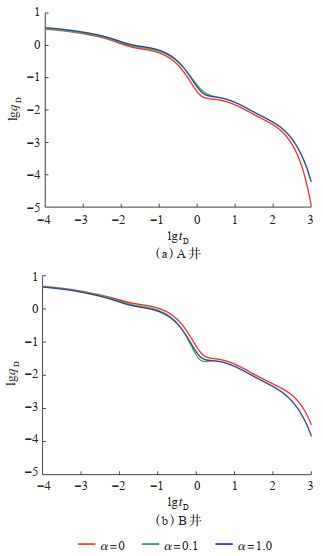
根据井底压力随时间的变化,利用式(17)绘制两井产量的递减曲线(图 7)。当发生裂缝干扰时,A井消耗的压差增大,B井消耗的压差减小,A井与B井产量的差值减小。从单井产能(图 7a)可看出,水平井裂缝干扰后,由于储层压力下降速度变快,产量增加。同时干扰系数越大,连通裂缝的数量越多,A井井底压力下降就越快,流体更易沿着裂缝流入A井,初期产量也就越高,在进入到晚期后,由于两井之间能量供给不足,裂缝连通条数增加导致产量下降更为明显。裂缝连通条数对未改造区线性流动阶段的产量几乎不产生影响,图 7b中B井产量变化规律与之相反。
|
下载原图 图 7 井间干扰系数对产量的影响(GD=0.1,FCDA = FCDB=20.0) Fig. 7 Effect of interwell interference coefficient on production |
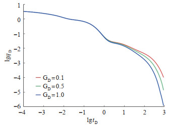
图 8是未改造区无因次启动压力梯度分别取0.1,0.5,1.0时A井产量的变化曲线。在改造区渗流阶段前无因次启动压力梯度对产量的影响较小,在生产的改造区拟稳态流、未改造区线性流、未改造区边界反映等阶段,启动压力梯度越大,流体在储层中的流动阻力越大,致密油井产量递减得则越快。
|
下载原图 图 8 启动压力梯度对产量的影响(α=0.1,FCDA = FCDB=20.0) Fig. 8 Effect of threshold pressure gradient on production |
裂缝导流能力对水平井产量的影响主要体现在前期。裂缝导流能力越小,水力裂缝中流体的流动能力越弱,因此前期阶段产量越小,产量曲线越靠下。由图 9可看出,裂缝导流能力的差异也会影响井间干扰系数对产量动态的影响。当两井裂缝导流能力相近时,α对产量的干扰相对较大,此时产量增减明显,这是因为导流能力差异小,裂缝连通后,其压力传播平衡需要的时间较短,井间连通的裂缝间流体流动更多。当两井裂缝导流能力存在较大差异时,井间干扰系数α对产量的影响相对较小,井间连通的裂缝间流体流动更困难。

|
下载原图 图 9 裂缝导流能力对水平井产量的影响(GD=0.1) Fig. 9 Effect of fracture conductivity on horizontal well production |
(1)基于致密油及页岩油水平井裂缝干扰渗流特征,考虑未改造区启动压力梯度、井间干扰系数、裂缝导流能力、井筒储集系数、表皮系数对井底压力和产能的影响,建立了考虑未改造区启动压力梯度的致密油水平井裂缝干扰模型。
(2)井间干扰系数对压力动态曲线的前期影响较大,裂缝干扰条数越多,改造区线性流持续的时间越长,改造区窜流发生得就越晚,同时改造区拟稳定流发生时间也越晚;未改造区启动压力梯度越大,拟稳定流发生时间越早;当两井裂缝导流能力相差较大时,井间干扰系数对压力动态的影响较小,导流能力越接近,井间干扰系数对压力动态的影响越明显。
(3)井间干扰系数越大,井底压力相对较低的水平井初期产量越高,但进入到晚期后,由于两井之间能量供给不足,反而产量下降越明显;未改造区无因次启动压力梯度对后期产量影响较大,无因次启动压力梯度越大,产量递减越快;裂缝导流能力越小,前期阶段产量越小,产量曲线越靠下,当两井裂缝导流能力相近时,井间干扰系数对产量的干扰程度相对较大,当两井裂缝导流能力存在较大差异时,井间干扰系数对产量的影响相对较小。
| [1] |
郭旭洋, 金衍, 黄雷, 等. 页岩油气藏水平井井间干扰研究现状和讨论. 石油钻采工艺, 2021, 43(3): 348-367. GUO Xuyang, JIN Yan, HUANG Lei, et al. Research status and discussion of horizontal well interference in shale oil and gas reservoirs. Oil Drilling & Production Technology, 2021, 43(3): 348-367. |
| [2] |
闫霞, 李小军, 赵辉, 等. 煤层气井井间干扰研究及应用. 岩性油气藏, 2015, 27(2): 126-132. YAN Xia, LI Xiaojun, ZHAO Hui, et al. Research on well interference of coalbed methane wells and its application. Lithologic Reservoirs, 2015, 27(2): 126-132. DOI:10.3969/j.issn.1673-8926.2015.02.020 |
| [3] |
罗攀, 张磊, 钟亚军, 等. 延长油田陆相页岩体积压裂SRV优化研究. 非常规油气, 2022, 9(4): 129-133. LUO Pan, ZHANG Lei, ZHONG Yajun, et al. SRV optimization for volumetric fracturing of continental shale in Yanchang Oilfield. Unconventional Oil & Gas, 2022, 9(4): 129-133. |
| [4] |
张意超, 陈民锋, 屈丹, 等. X油田特低渗透油藏井网加密效果预测方法. 岩性油气藏, 2020, 32(1): 144-151. ZHANG Yichao, CHEN Minfeng, QU Dan, et al. Prediction method of well pattern infilling effect for ultra-low permeability reservoir in X oilfield. Lithologic Reservoirs, 2020, 32(1): 144-151. DOI:10.12108/yxyqc.20200116 |
| [5] |
BHP E R, BLASINGAME T A. Optimizing the development of the Haynesville Shale: Lessons learned from well-to-well hydraulic fracture interference[R]. URTEC 2670079, 2017.
|
| [6] |
蒋廷学, 王海涛, 卞晓冰, 等. 水平井体积压裂技术研究与应用. 岩性油气藏, 2018, 30(3): 1-11. JIANG Tingxue, WANG Haitao, BIAN Xiaobing, et al. Volume fracturing technology for horizontal well and its application. Lithologic Reservoirs, 2018, 30(3): 1-11. DOI:10.12108/yxyqc.20180301 |
| [7] |
封猛, 胡广文, 丁心鲁, 等. 吉木萨尔凹陷致密储层水平井压裂井间干扰分析. 石油地质与工程, 2018, 32(3): 108-110. FENG Meng, HU Guangwen, DING Xinlu, et al. Well interference analysis during horizontal well fracturing of dense reservoirs in Jimusar Sag. Petroleum Geology and Engineering, 2018, 32(3): 108-110. |
| [8] |
李继庆, 刘曰武, 黄灿, 等. 页岩气水平井试井模型及井间干扰特征. 岩性油气藏, 2018, 30(6): 138-144. LI Jiqing, LIU Yuewu, HUANG Can, et al. Multi-stage fracturing horizontal well interference test model and its application. Lithologic Reservoirs, 2018, 30(6): 138-144. DOI:10.12108/yxyqc.20180617 |
| [9] |
MOLINA O, ZEIDOUNI M. Analytical approach to determine the degree of interference between multi-fractured horizontal wells[R]. SPE 185765, 2017.
|
| [10] |
YU Wei, WU Kan, ZUO Lihua, et al. Physical models for interwell interference in shale reservoirs: Relative impacts of fracture hits and matrix permeability[R]. San Antonio, Texas: SPE/AAPG/SEG Unconventional Resources Technology Conference, 2016.
|
| [11] |
杨兆中, 苏洲, 李小刚, 等. 水平井交替压裂裂缝间距优化及影响因素分析. 岩性油气藏, 2015, 27(3): 11-17. YANG Zhaozhong, SU Zhou, LI Xiaogang, et al. Fracture spacing optimization for horizontal well alternating fracturing andinfluencing factors. Lithologic Reservoirs, 2015, 27(3): 11-17. DOI:10.3969/j.issn.1673-8926.2015.03.002 |
| [12] |
KHODABAKHSHNEJAD A. Impact of Frac Hits on Production Performance: A case study in Marcellus Shale[R]. SPE 195296, 2019.
|
| [13] |
GALA D P, MANCHANDA R, SHARMA M M. Modeling of fluid injection in depleted parent wells to minimize damage due to frac-hits[R]. URTEC 2881265, 2018.
|
| [14] |
李凌川, 李克永. 泾河油田水平井密切割增能体积压裂探索及认识. 非常规油气, 2022, 9(4): 114-122. LI Lingchuan, LI Keyong. Exploration and cognition of intensive staged energizing volume fracturing for horizontal wells in Jinghe Oilfield. Unconventional Oil & Gas, 2022, 9(4): 114-122. |
| [15] |
蔡晖, 屈丹, 陈民锋. 组合井网储量动用规律及水平井加密合理技术策略: 以渤海HD油田为例. 岩性油气藏, 2021, 33(4): 147-155. CAI Hui, QU Dan, CHEN Minfeng. Reserve producing law of combined well pattern and technology strategy of horizontal well infilling: A case study from HD oilfield in Bohai Sea. Lithologic Reservoirs, 2021, 33(4): 147-155. DOI:10.12108/yxyqc.20210416 |
| [16] |
赵二猛. 体积压裂水平井试井分析及产能预测研究[D]. 大庆: 东北石油大学, 2017. ZHAO Ermeng. Study of well test analysis and productivity prediction for multiple-fractured horizontal wells[D]. Daqing: Northeast Petroleum University, 2017. |
| [17] |
任岚, 黄鑫. 致密油藏体积压裂水平井分区复合产能模型. 大庆石油地质与开发, 2018, 37(2): 157-163. REN Lan, HUANG Xin. Composite productivity model for the volume fractured horizontal well districts in tight oil reservoirs. Petroleum Geology and Oilfield Development in Daqing, 2018, 37(2): 157-163. |
| [18] |
苏皓, 雷征东, 张荻萩, 等. 致密油藏体积压裂水平井参数优化研究. 岩性油气藏, 2018, 30(4): 140-148. SU Hao, LEI Zhengdong, ZHANG Diqiu, et al. Volume fracturing parameters optimization of horizontal well in tight reservoir. Lithologic Reservoirs, 2018, 30(4): 140-148. DOI:10.12108/yxyqc.20180417 |
| [19] |
刘博, 徐刚, 纪拥军, 等. 页岩油水平井体积压裂及微地震监测技术实践. 岩性油气藏, 2020, 32(6): 172-180. LIU Bo, XU Gang, JI Yongjun, et al. Practice of volume fracturing and microseismic monitoring technology in horizontal wells of shale oil. Lithologic Reservoirs, 2020, 32(6): 172-180. DOI:10.12108/yxyqc.20200617 |
| [20] |
FREDERICK J L, KELKAR M. Decline-curve analysis for solution-gas-drive reservoirs[R]. SPE 94859, 2005.
|
| [21] |
何家欢, 张苏, 刘生国, 等. 关于Laplace数值反演Stehfest算法适用性的一点思考. 油气井测试, 2015, 24(4): 18-20. HE Jiahuan, ZHANG Su, LIU Shengguo, et al. Thinking about the numerical inversion of Laplace transform and usability of Stehfest algorithm. Well Testing, 2015, 24(4): 18-20. |
 2024, Vol. 36


